1
2.5 – Testing the CLUTCH & DELAY Switch Input
Set the SELECT Switch to DIAGNOSTICS
Press and HOLD the PROGRAM Switch until display reads RELEASE. Release the PROGRAM Switch at this
time. The controller is now in the diagnostic mode.
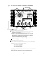
To perform CLUTCH (2-step) Input test set the .001 switch to 2.
At this time the DISPLAY will read CLUTCH. If +12 volts is connected to the CLUTCH input terminal the
Display would flash the message ACTIVE. Use this test to verify clutch/2-step switches on the bike.
To exit diagnostics turn the .001 switch to 7. Then press and release the PROGRAM switch.
2.6 – Testing AUTO-SHIFT & SEQUENCING Activation Input
Set the SELECT Switch to DIAGNOSTICS
Press and HOLD the PROGRAM Switch until display reads RELEASE. Release the PROGRAM Switch at this
time. The controller is now in the diagnostic mode.
To perform AUTO & Sequencing Activation Input test set the .001 switch to 4.
At this time the DISPLAY will read AUTO. If +12 volts is connected to the Auto Activation terminal the
Display will flash the message ACTIVE. Use this test to verify the Auto Shift & Sequencing activation switch.
To exit diagnostics turn the .001 switch to 7. Then press and release the PROGRAM switch.
2.7 – Testing Shift Override Input
Set the SELECT Switch to DIAGNOSTICS
Press and HOLD the PROGRAM Switch until display reads RELEASE. Release the PROGRAM Switch at this
time. The controller is now in the diagnostic mode.
To perform Manual Shift Input test set the .001 switch to 5.
At this time the DISPLAY will read SHIFT. If +12 volts is connected to the SHIFT TERMINAL #1 or SHIFT
TERMINAL #1 and SHIFT TERMINAL #2 are connected the Display will flash the message ACTIVE.
Use this test to verify the Manual Shift activation switch.
To exit diagnostics turn the .001 switch to 7. Then press and release the PROGRAM switch.
2.8 – Turning the Timed Ignition Stutter Option On/Off
Set the SELECT Switch to DIAGNOSTICS
Press and HOLD the PROGRAM Switch until display reads RELEASE. Release the PROGRAM Switch at this
time. The controller is now in the diagnostic mode.
Set the .001 switch to 6. At this time the display will read one of the following.
OPT. ON – This means the Timed Ignition Stutter Option is ON. By turning this option on the Ignition will
stagger fire the ignition coils for the amount of time set with the TIMER DURATION. The ignition stutter will
NOT begin until the TIMER DURATION has timed out. While the ignition stutter is active each cylinder will
fire once and skip one fire sequence. Please NOTE that all other features and TIMERS remain active during this
time.
OPT. OFF – This means the Timed Ignition Stutter is OFF. No ignition stagger fire will occur during TIMER
ACTIVATION.
NOTE – The Timer Output Terminal is NOT affected by this setting in any way.
To toggle between ON and OFF press and release the PROGRAM button.
Page 14