1
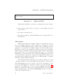
CHAPTER 7. SPI : LCD DISPLAY
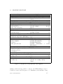
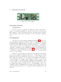
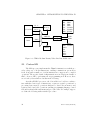
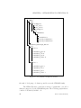
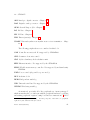
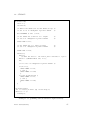
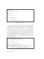
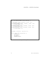
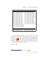
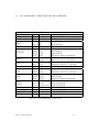
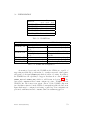
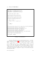
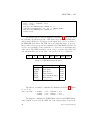
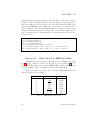
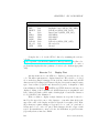
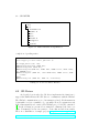
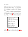
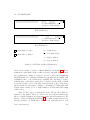
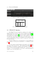
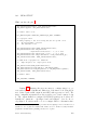
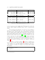
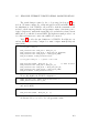
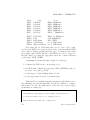
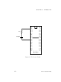
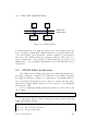
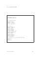
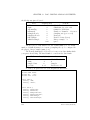
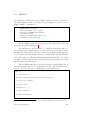
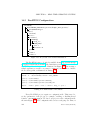
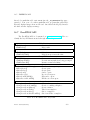
TFT Pin
VCC
BKL
RESET
RS
MISO
MOSI
SCLK
LCD CS
SD_CS
GND
STM32 Pin
5V
PA1
PC1
PC2
PB14
PB15
PB13
PC0
PC6
GND
Function
Power – 5 Volts
Backlight control (GPIO_PIN_BKL)
LCD Reset (GPIO_PIN_RST)
Data/Control (GPIO_PIN_DC)
SPI2 MISO
SPI2 MOSI
SPI2 CLK
LCD select (GPIO_PIN_SCE)
SD card select
Ground
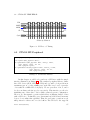
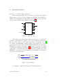
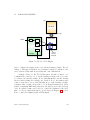
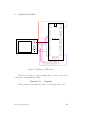
Figure 7.3: TFT Pin Assignment
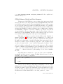
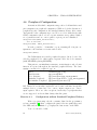
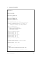
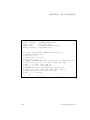
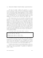
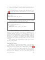
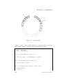
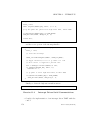
Complete the code for the ST7335 driver by examining the reference
code at
https://github.com/adafruit/Adafruit-ST7735-Library. You’ll need to
complete the initialization code data structure. To test your code, write a
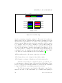
program that displays the three primary colors in a cycle, with an appropriate
delay.
Exercise 7.2
Display Text
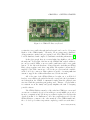
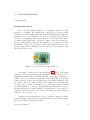
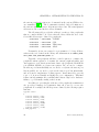
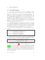
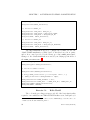
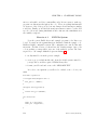
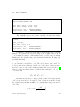
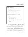
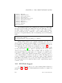
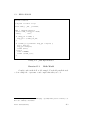
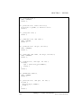
An important use for an LCD is to display log messages from your
code. The first requirement is to display characters. The reference code cited
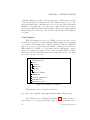
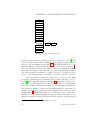
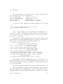
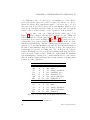
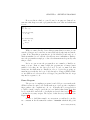
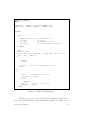
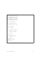
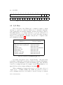
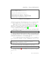
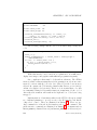
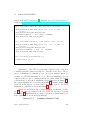
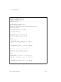
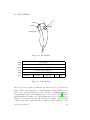
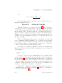
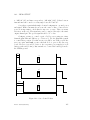
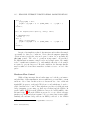
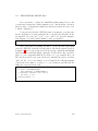
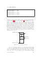
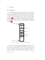
above includes a simple bit-mapped font glcdfont.c which defines the ASCII
characters as 5x7 bit maps (each character is placed in a 6x10 rectangle leaving
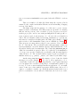
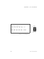
space between lines (3 pixels) and characters (1 pixel). A fragment of this
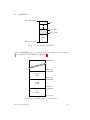
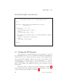
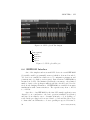
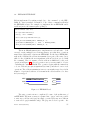
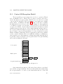
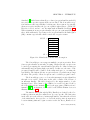
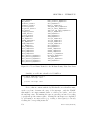
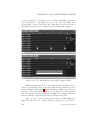
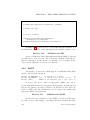
font is illustrated in Figure 7.1. ASCII 0 is a NULL character and hence not
displayed. Many of the low-numbered ASCII characters are unprintable and
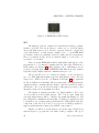
hence either left blank or filled with a default glyph. Consider the character
for ’A’ (ASCII 65) also illustrated.
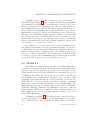
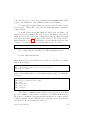
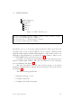
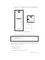
Write a routine to display a single character at a specific location defined by the upper left corner of the character – remember that (0,0) is the
upper left corner of the display and (127,159) is the lower right corner. Writing a character requires writing a foreground color to each “on” pixel and a
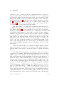
background color to each “off” pixel. Each character should occupy a 6x10
region. It is much faster to write a block to the LCD than one pixel at a time
(especially when we introduce DMA.
102
Revision: 1396a85 (2013-01-07)