1
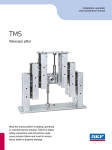
Installation, operation and maintenance manual TLG/THG Telescopic pillars Read this manual before installing, operating or maintaining this actuator. Failure to follow safety precautions and instructions could cause actuator failure and result in serious injury, death or property damage. Technical Instructions Telemag THG/TLG Telescopic column DC Content 1 General . . . . . . . . . . . . . . . . . . . . . . . . . . . . . . . . . . . . . . . . . . . . . . . . . . . . . . . . . . . . . . .2 1.1 Using the Technical Instructions . . . . . . . . . . . . . . . . . . . . . . . . . . . . .2 1.2 Explanation of symbols . . . . . . . . . . . . . . . . . . . . . . . . . . . . . . . . . . .2 1.3 Correct use . . . . . . . . . . . . . . . . . . . . . . . . . . . . . . . . . . . . . . . . . . . .2 1.4 Ambient conditions . . . . . . . . . . . . . . . . . . . . . . . . . . . . . . . . . . . . . .2 2 Function . . . . . . . . . . . . . . . . . . . . . . . . . . . . . . . . . . . . . . . . . . . . . . . . . . . . . . . . . . . . . .3 2.1 General function . . . . . . . . . . . . . . . . . . . . . . . . . . . . . . . . . . . . . . . .3 2.2 Construction . . . . . . . . . . . . . . . . . . . . . . . . . . . . . . . . . . . . . . . . . . .3 3 Installation and startup . . . . . . . . . . . . . . . . . . . . . . . . . . . . . . . . . . . . . . . . . . . . . . . . . .4 3.1 Scope of delivery . . . . . . . . . . . . . . . . . . . . . . . . . . . . . . . . . . . . . . . .4 3.2 Installation . . . . . . . . . . . . . . . . . . . . . . . . . . . . . . . . . . . . . . . . . . . .4 3.3 Electrical connection . . . . . . . . . . . . . . . . . . . . . . . . . . . . . . . . . . . . .5 3.4 Start up . . . . . . . . . . . . . . . . . . . . . . . . . . . . . . . . . . . . . . . . . . . . . .5 4 Operation . . . . . . . . . . . . . . . . . . . . . . . . . . . . . . . . . . . . . . . . . . . . . . . . . . . . . . . . . . . . .6 4.1 Controlling an actuator . . . . . . . . . . . . . . . . . . . . . . . . . . . . . . . . . . .6 5 Maintenance and care 5.1 Maintenance . . 5.2 Care . . . . . . . . 5.3 Warranty . . . . 5.4 Disposal . . . . . 5.5 Liability . . . . . . . . . . . . . . . . . . . . . . . . . . . . . . . . . . . . . . . . . . . . . . . . . . . . . . . . . . . . .6 . . . . . . . . . . . . . . . . . . . . . . . . . . . . . . . . . . . . . . . .6 . . . . . . . . . . . . . . . . . . . . . . . . . . . . . . . . . . . . . . . .6 . . . . . . . . . . . . . . . . . . . . . . . . . . . . . . . . . . . . . . . .6 . . . . . . . . . . . . . . . . . . . . . . . . . . . . . . . . . . . . . . . .6 . . . . . . . . . . . . . . . . . . . . . . . . . . . . . . . . . . . . . . . .6 6 Technical data . . . . . . . . . . . . . . . . . . . . . . . . . . . . . . . . . . . . . . . . . . . . . . . . . . . . . . . . . .7 7 Troubleshooting and fault elimination . . . . . . . . . . . . . . . . . . . . . . . . . . . . . . . . . . . . . .8 Reference standards: EN 60601-1 EN 55011 UL 2601 SKF Actuation System (Liestal) AG Oristalstrasse 97 CH- 4410 Liestal Phone +41/ 61/ 925 41 11 Fax +41/ 61/ 921 37 04 e- mail actuators@skf.com 5 31e1655_0701 Technical Istructions Telemag THG/ TLG 1 General 1.1 Using the Technical Instructions The Technical Instructions are intended for designers or technicians who use the Telemag telescopic actuator (referred to below as Telemag) in their products and for fitters working with the Telemag. The Technical Instructions contain all relevant information on this SKF product. We reserve the right to make changes which are in the interest of technical progress. Please read the Technical Instructions carefully and, above all, pay careful attention to the Safety Instructions. The Technical Instructions should be used for drawing up the User Manual for the end product. This symbol is used to indicate operations and states which could endanger life and limb. Follow the instructions precisely! 1.2 Explanation of symbols The symbols opposite are used in the Technical Instructions to highlight possible dangers and important notes. This symbol provides the user with useful information. Where eccentric loads are involved, the permissible maximum load decreases. Please observe the permissible load on the load diagram contained in the datasheet. If an eccentric overload occurs, the actuator can be damaged. The load can tip sideways. 1.3 Correct use The Telemag telescopic actuators must only be used for lifting purposes. The actuators should only be subjected to compressive loads. No other usage is permitted. Conversions or modifications to the linear actuators or the electrical installation are not permitted. Only original spare parts and accessories from SKF may be used. The actuator is intended for use with a SKF control system. The unit is only suitable for indoor use and must not be subjected to the elements. T h e Telemag telescopic actuator must not be operated in an explosive atmosphere. For transport purposes, the Telemag can be loaded with a pull force of up to 50 kg for a short period. The maximum centric load specified on the data label and the permissible eccentric load specified in the transverse load diagram must not be exceeded. A push actuator must never be used to pull. The actuator may be destroyed if these instructions are not observed. 1.4 Ambient conditions Operation Temperature 10 °C to 40 °C Humidity max. 85% Storage / transport Temperature -20 °C to 40 °C Humidity max. 95% Operating mode Intermittent 10%; 1 min ON / 9 min OFF The actuator has been designed for intermittent operation. If a higher duty cycle is required, contact SKF Actuation System (Liestal) AG. 531e1655_0701 page 2/8 Technical Istructions Telemag THG/ TLG 2 Function 2.1 General function The Telemag is an electrical telescopic actuator which uses virtually play-free guide tubes. It has been designed for holding and moving centric and eccentric loads. A DC motor with worm gear controls a threaded spindle via a bevel gear. A threaded nut moves up and down on the spindle, which is secured to the push tube and thereby generates the feed motion. The telescopic tubes are retracted and run out depending on the direction of the motor. The characteristics of the permanent magnet motor means that the speed is load-dependent. 2.2 Construction The power cable is integrated into the Telemag. Protection from thermal or electrical overload is only guaranteed if a SKF control unit is connected. The actuator has no internal limit switches. It is protected from thermal and electrical overload by a connected SKF control unit. Control unit The DC motor is fed using an external SKF control unit or a master actuator. These components also determine the running direction of the actuator, depending on the polarity of the DC current. The actuator is moved via the control unit and any connected control elements. The first failure safety of the overall system must be checked in the end product in order to rule out risks to life/limb and property. 531e1655_0701 The Telemag has extensive protection against faults. First failure safety cannot be ensured, however, since unpredictable faults - e.g. to a control device - can result in slow, uncontrolled movements. page 3/8 Technical Istructions The protective conductor in the cable feedthrough is not connected to the actuator's aluminium tubes. Telemag THG/ TLG 3 Installation and startup 3.1 Scope of delivery The Telemag consists of: The entire lifting column Options Integrated current cut-off Encoder (Hall sensor) Cable feedthroughs 230 V, 6 A Potentiometer (not possible on all types) Accessories Only use the screws recommended (Quality 10 . 9 ) . Observe the minimum screw-in depth and the torque specified on the datasheet. When using your own mounting plates, you must ensure that the base plates are supported over their entire surface - this will distribute the force over the entire area. Otherwise, there is a risk of the base plates fracturing. 3.2 Handswitch Desk switch Footswitch Control units Mounting plates Fastening screws Installation The Telemag can be secured to either SKF mounting plates (see 3.1 Accessories) or the customer's own plates. ` Remove the transportation screws (4 pcs.) ` Fasten the mounting plates onto the aluminium tubes using the four bores (auxiliary plates are fitted to the end faces of the outer and inner tubes). screws see table page 5 ø20 ø8,5 ø22 ø8,5 ø20,5 screws see table page 5 Fig. 1 – Installation 531e1655_0701 page 4/8 Technical Istructions During installation, ensure that no objects or parts of the body are trapped between the mounting plate of the internal tube and the outer tube during retraction. If necessary, a mechanical protection device should be installed, depending on where the device is being used. Danger of crushing! Telemag THG/ TLG THG TLG Screw 4 x M6x25 4 x M10x30 Screw-in depth min. 22 mm min. 25 mm Strength class 10.9 10.9 Tightening torque 9 Nm 40 Nm Any subsequent fastening bores in the aluminium tubes may only be made by SKF. The sides of the tubes must not be scratched, otherwise the tube guide will be damaged. This can result in malfunctions. The power cable must be also be strainrelieved on the object on which the actuator is installed. 3.3 Electrical connection All cables must be secured so that no forces act on the plugs. Motor Laufrichtung Motor direction Plugs which are poorly aligned may allow liquids to penetrate which can damage the actuator. The sealing rings of the connecting plug must be checked for damage each time they are connected, and should be greased lightly with Klübersynth VR 69252, order no. 521023, to make installation easier. Damaged seals must be exchanged. The use of other gliding agents can lead to the plastic being damaged. Electric cables should not be exposed to the risk of pinching, or to bending or tensile loads. Direct connection to a voltage supply is not permitted, since this can cause damage to the actuator. Fig. 2 – Connection The supply voltage and control unit are connected via the jack plug to a SKF control unit or a master actuator. Connected load: 24 V DC, 6 A; see type plate The power cable, when plugged into the socket, is strain-relieved and sealed. The jack plug has a bayonet lock which must be fitted correctly into the connection socket and locked in position. To lock the jack plug, use SKF Special Key No. 140375. The jack plug must be plugged right into the opening and be locked in position with the bayonet lock. Important! Risk of personal injury! When the actuator is being actuated, ensure that physical objects or parts of the body cannot become trapped. If necessary, a mechanical protection device should be installed, depending on where the device is being used. Fig. 3 – Plugging in the control cable 3.4 Start up The Telemag is ready for operation once all mechanical and electrical installation work has been completed correctly. The actuator is switched using the handswitch or footswitch connected to the control unit, depending on the design. 531e1655_0701 page 5/8 Technical Istructions Important! The load specified on the type plate must not be exceeded. Otherwise the actuator may be damaged. Telemag THG/ TLG 4 Operation 4.1 Controlling an actuator Actuators are controlled via a suitable SKF control unit or a master actuator (e.g. type Matrix MAX6). The actuator travels for as long as the current feed lasts, or until the actuator reaches a terminal position. Further information can be found in the Technical Instructions for the relevant control unit or actuator. 5 Maintenance and care 5.1 Maintenance A Telemag has been designed for a service life of 20,000 double strokes of length 300 mm (this applies for a maximum centric load as per the data label). The Telemag requires no maintenance during this period. In-house tests must be performed if other requirements relating to service life are specified. 5.2 Care Protection from water, cleaning, disinfecting Ensure that no liquids are allowed to penetrate the connections! The actuator could be damaged by liquid entering it. The actuator is not suitable for automatic washing systems. Degree of protection IP30 is only achieved if the device is installed correctly in the end product. If an actuator becomes dirty, it should be cleaned immediately in order to prevent the accretion of residues on the guide tubes. Use a damp cloth and water with a little isopropyl alcohol for manual cleaning. Washing water with chemical additives must be pH-neutral. Excessively acidic or alkaline washing water can permanently damage the metal and plastic components of the actuator. High-pressure steam cleansing equipment must not be used. 5.3 Warranty Assuming that the operating conditions are complied with and units have no mechanical damage resulting from incorrect handling, a warranty of 12 months from the date of delivery will apply for all mechanical and electrical components. 5.4 Disposal The control unit components and actuators may be returned to SKF Actuation System (Liestal) AG, for disposal. 5.5 Liability In every case, the owner or operator of the unit shall be liable for its correct functioning if it has been incorrectly installed, maintained or repaired by persons who are not employed by the SKF Service Department or if the unit has not been used in accordance with the specified application. SKF Aktiengesellschaft shall not be liable for any damage resulting from failure to observe these instructions. These instructions shall not be regarded as an extension of the warranty and liability terms set out in the Conditions of Sale and Supply of SKF Aktiengesellschaft. 531e1655_0701 page 6/8 Technical Istructions Telemag THG/ TLG 6 Technical data Technical data see type plate The manufacturer reserves the right to modify technical data, without any special notification, in order to keep pace with advances in technology. SKF will be pleased to provide information about current specifications, possible changes or extensions. Fig. 4 – Dimensions THG Fig. 5 – Dimensions TLG 531e1655_0701 page 7/8 Technical Istructions Telemag THG/ TLG 7 Important! Any work on the units and connections may only be undertaken when the mains plug has been disconnected. Troubleshooting and fault elimination Fault Cause Remedy Actuator not working No mains voltage present Check the mains voltage Poor connector contact Plug the mains plug in correctly or check the the terminal connections Plug in the control device plug correctly. Power cable faulty Return the actuator to the SKF Service Depart- Control device or control element faulty Exchange the control device or control element. Motor faulty Return the actuator to the SKF Service Depart- Markedly reduced tuaspeed Motor, gears or Immediately take the ac- nut faulty tor out of operation and return it to the SKF Service Department. Very loud tuarunning noise Motor, gears or Immediately take the ac- nut faulty tor out of operation and return it to the SKF Service Department. Play in the guidance system ment Gliding elements worn Return the actuator to the SKF Service Depart- ment ment Observe the instructions in the relevant customer documentation. If you are unable to eliminate a fault, contact Magnetic AG, Liestal. 531e1655_0701 page 8/8 The Power of Knowledge Engineering Seals Bearings and units Mechatronics Lubrication systems Services Drawing on five areas of competence and application-specific expertise amassed over more than 100 years, SKF brings innovative solutions to OEMs and production facilities in every major industry worldwide. These five competence areas include bearings and units, seals, lubrication systems, mechatronics (combining mechanics and electronics into intelligent systems), and a wide range of services, from 3-D computer modelling to advanced condition monitoring and reliability and asset management systems. A global presence provides SKF customers uniform quality standards and worldwide product availability. Please contact: SKF Actuation System (Liestal) AG Oristalstrasse 97 4410 Liestal Switzerland Tel.: +41 61 925 4111 Fax: +41 61 921 3704 actuators@skf.com ® SKF is a registered trademark of the SKF Group. © SKF Group 2010 The contents of this publication are the copyright of the publisher and may not be reproduced (even extracts) unless prior written permission is granted. Every care has been taken to ensure the accuracy of the information contained in this publication but no liability can be accepted for any loss or damage whether direct, indirect or consequential arising out of the use of the information contained herein. skf.com