1
Installation and Operation Manual
X-TMF-5850E-MFC-eng
Part Number: 541B102AAG
September, 2009
Section 4 Maintenance &
Troubleshooting
Brooks® Model 5850E
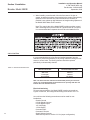
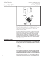
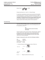
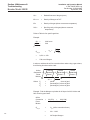
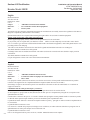
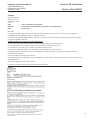
Then Dp = 64.7 - 44.7 = 20psi
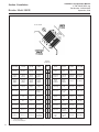
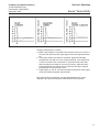
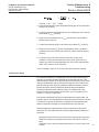
4. Using the nomograph, locate the pressure drop (psi) on the vertical line
marked "Dp" (Point A).
5. Locate the Nitrogen equivalent flow rate (sccm Nitrogen) on the vertical
line marked "QNitrogen" (Point B).
6. Draw a line connecting Dp and QNitrogen and extend it to the baseline.
Mark this point (Point C).
7. Locate inlet pressure (psia) on the vertical line marked "Pin" (Point D).
8. Draw a line connecting Pin (Point D) and baseline (Point C) and then
extend this line to the vertical line marked Do (orifice diameter, inches)
(Point E).
9. This point on the line is the minimum orifice size for the given
conditions. If this point is between two orifice sizes, select the next
largest size orifice to ensure adequate flow. If the orifice selected falls
below .0013, choose .0013 size orifice.
For the example in Figure 4-5, the .007 size orifice would be selected.
4-7 Restrictor Sizing
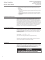
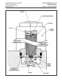
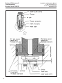
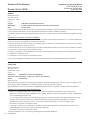
The restrictor assembly is a ranging device for the sensor portion of the
controller. It creates a pressure drop which is linear with flow rate. This
diverts a sample quantity of the process gas flow through the sensor. Each
restrictor maintains the ratio of sensor flow to restrictor flow, however the
total flow through each restrictor is different. Different restrictors (micron
porosity and active area) have different pressure drops and produce
controllers with different full scale flow rates. For a discussion of the
interaction of the various parts of the controller, you are urged to review
Section 3-1 (Theory of Operation).
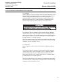
If the restrictor assembly has been contaminated with foreign matter, the
pressure drop vs. flow characteristics will be altered and it must be cleaned
or replaced. It may also be necessary to replace the restrictor assembly
when the mass flow controller is to be calibrated to a new flow rate.
Restrictor assembly replacement should be performed only by trained
personnel. The tools required for the removal/replacement procedure are
as follows:
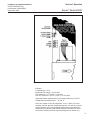
Appropriate size wrench for the removal of the inlet process connection
Restrictor removal tool (contained in service tool kit P/N S-778-D-017AAA)
Restrictor O-ring, refer to the spare parts Section 5, for the correct part
number.
4-21