1
VMM Setup and Use
5. VMM Setup and Use
This section reviews common practices that should be used when developing a vehicle
electrical system that uses VMMs.
5.1. Input Considerations
As discussed in Section 3, there are four different types of inputs available on the
VMM. To recap, these are
•
Digital switch-to-ground type
•
Digital switch-to-battery type (programmable)
•
Digital switch-to-ground type with power control
•
Analog type
When designing the wire harness for a vehicle the main input item that has to be
considered is the “Digital switch-to-ground type with power control” or simply
“Power Control Inputs”. These are inputs 1 to 5 and they behave like any other
switch-to-ground input on the unit except that they control the power to the
VMM. This means that at least one of these inputs must be active (or grounded)
in order to power up a VMM in the vehicle.
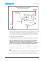
In addition, input 1 on all the VMMs in a vehicle is reserved to be “Master
Power”. This is a reference input that the VMM uses to perform additional tasks.
Input 1 on all VMMs in a system must be connected to the same source, which
means that when this source is active all VMMs in the vehicle will be powered
on. Typically this source would be a dashboard switch called “Master Power” or
the “auxiliary”/“run” position of a key switch. When this “Master Power” input
is active the following tasks are performed by the VMM:
•
Plug and Play system check
•
VMM Communication failure check
VMM Communication Failure and Plug and Play checks require that all VMMs
defined in the system are powered when the check occurs. The only way to
Hardware Manual
Page 19 of 50