1
University of Saskatchewan
Electrical Engineering Laboratory Equipment Manual
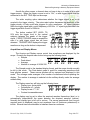
The display format is normally left set to YT; this is the normal volts vs. time
display of the scope. When you wish to display one waveform vs. another, set the
format to XY. When in the XY mode, channel 1 is the X (horizontal) waveform, and
channel 2 is the Y (vertical) waveform. While in this display mode, the channel 1
volts/div and position knobs control the horizontal scale and position, while the channel
2 volts/div and position knobs control the vertical scale and position.
The contrast softkeys change the display contrast of the scope.
Measurements and Cursors
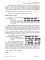
A number of automated measurements are possible when the measure menu
button is pressed:
• Source/Type
• Any four of the following
measurements: frequency, period, mean (average), pk-pk, cyc rms (true
rms computed over one cycle), rise time, fall time, positive width, negative
width, or none
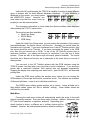
The four measurement readout windows adjacent to the bottom four softkeys list
the channel being measured (CH1 / CH2), the specific measurement (as listed above),
and the measured quantity. The top softkey selects between the source channel
selection mode or the measurement type selection mode. When Source is selected, the
source channels in the measurement windows become highlighted. Pressing one of the
bottom four softkeys will toggle the selected source channel, but will not change the
measurement type. When Type is selected, the measurement type will be changed by
the bottom four softkeys, but not the source channel.
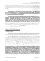
A set of voltage or time cursors is available by pressing the Cursor menu button.
The following items then appear:
• Cursor type: off/voltage/time
• Source CH1 / CH2 / MATH / Ref
A / Ref B
The only deficiency that this scope has
is its cursors. Unfortunately, only the voltage
or time cursors can be displayed, but not both
at once. This may be an issue, depending on the lab you are performing. The menu
choices available here are self-explanatory. To move the cursors, use the channel 1 &
2 vertical position controls. When either the voltage or time cursors are active, the
position of each cursor as well as the difference between them (in either volts or
seconds) will be displayed at the right side of the display. In the case of the time
cursors, 1/difference will also be displayed.
Printing
Revised: Sept. 2009, J. Kowalski
Page 12 of 25