1
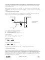
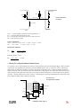
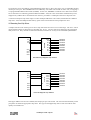
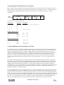
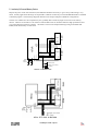
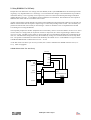
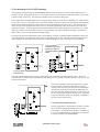
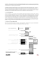
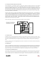
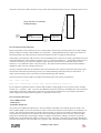
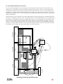
Vcc input leakage current input current Vcc R PU I PU RESET IP0H <= 10uA Pull-Up Resistors On Port 0 I SYSH Port 0 V IN = V IHMIN System. 167 VIHMIN = Lowest voltage on pin that will be accepted as a ‘1’ ISYSH = Current sunk into bus devices etc. IP0H = Current that can be drawn from 167’s Port 0 at VIHMIN RPU = Pull up resistor on P0 From 167 Databook: VIHMIN = 0.2 x Vcc + 0.9v - 0,1V => 1.8V <= VIHMIN =< 2.0V Vcc = 5V +/-10% => 4.5V =< VCC =< 5.5V Pull Up Resistor Calculation RPu < VPU IPD = VCCMIN - VIHMIN ISYSH - IP0H Example: ISYSL = 50uA RPU < 4.5v - 1.8v 50uA - 10uA = 67.6K 1.4 Setting The Configuration Without Pulldown Resistors It is possible to use a simple analog-type switch to set the pattern on port 0 in external bus designs. Here, the links to ground are only applied to the port 0 pins when the /RESIN signal is low, i.e. the 166 is in reset. The D-type latch powers up with the Q output low so that the link pattern is applied to port 0. When the RESET signal goes high to release the CPU, the switch is kept active until the first rising edge of ALE at the start of the first bus cycle. At this point the CLK signal forces the latch to set Q high so that the link pattern is removed and the bus operates normally. Waiting until the first ALE is essential - controlling the switches from /RESIN alone could result in the CPU reading the pattern after it has been removed! Active Port 0 Configuration Scheme 167 Quick Switch P0L.0 Bootstrap Mode Bus Mode P0L.7 /RESIN /EN Vcc S D ALE Links Q 74x74 GND /CLR CLK /Q RESET CIRCUIT 166 Designers Guide - Page 14