1
US 8,581,876 B1
7
8
functions performed by the system. Touching the screen 40
(See FIG. 1) at the location of an icon image selects that
“Presentations,” installed in the “C” position in the receptacle
card 12, includes a number of folders or other ?les designated
memory device or initiates a command or function repre
by the reference numbers 142, 146, 150, 154, and 158 in this
sented by the touched icon image. In some cases touching the
example. Each folder or ?le may be described by textual
screen 40 tWice or in tWo different locations, or dragging
and/or numeric indices respectively 144, 148, 152, 156, and
one’s ?nger mat be required and implemented in the operat
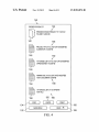
160 as shoWn in FIG. 4. For example, folder 142 entitled
ing or application program to initiate or perform the com
Presentations, Project “A,” is dated Dec. 10, 2012 and occu
pies 12,000 Kilobytes (KB) of memory space, as described by
the description indices 144. In another example, a PoWer
Point® ?le 146 entitled simply “Project B” is dated Feb. 1,
2013 and occupies 13,000 KB ofmemory space, as described
by the indices 148. Other entries in the device directory dis
play 140 include an Attendee List 150, Which may be, for
example, an Excel® spreadsheet 152, a Narrative 154/156,
mand or function (see FIGS. 7, 8, and 9). Included at the loWer
end of the screen 40, in most of the screen displays are a set of
command buttons for the functions MAIN MENU 102,
COPY 104, PASTE 105, PRINT 106, and BACK 108, all of
Which are Well-knoWn, intuitive commands. In addition, at
the upper end of the screen 40 may be an indicator 110 such
as an LED behind the screen or an image illuminated by a
and another Attendee List 158/160 in Adobe format. Note:
PowerPoint@ and Excel® are registered trademarks of
Microsoft® Corporation. Adobe is either a registered trade
mark or a trademark of Adobe Systems Inc. Touching the
light emitting device behind the screen 40 to indicate opera
tion of a battery charger, the condition of the battery, and the
like. Other indicators of this type may also be included in
alternate embodiments.
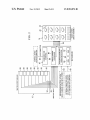
Also on the main menu display 100 in FIG. 3 are eight
icons, bearing reference numbers 124, 126, 128, 130, 132,
134, 136, and 138. Each icon 124-138 corresponds to one of
the receptacles 28 in the system 10 for receiving a memory
device 30 for storage in the system. When a memory device
receptacle 28 is occupied, the memory device icon 112 may
become illuminated, change color, or display an altered
image to indicate the occupation of the receptacle 28 in the
receptacle card 12. Each of these memory icons 112 may be
accompanied by a horiZontal bar graph image 114 that may
have a darkened (or colored) portion 116 representing an
occupied portion of the memory capacity of the memory
device 30 and an undarkened (or uncolored) portion 118
device directory display 140 at the location of the icon image
20
cases touching the directory display 140 tWice or in tWo
different locations, or dragging one’s ?nger is required to
initiate the command or function. As in screen 40 a set of
25
30
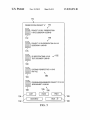
the directory of the contents of a selected folder 142 in a
selected memory device connected to the embodiment of
FIG. 1. The selected folder 142 entitled Presentations
include a number of documents 172, 176, 180, . . . 188,
respectively identi?ed by the indicia 174, 178, 182, . . . 190 in
of the memory device 30. For example, the bar graph 114 for
memory device 126 indicates 0.8 GB (giga byte) occupied
the same manner is described in FIG. 4. Touching the loWer
35
end of the display 170 at the location of a button image
initiates the corresponding command or function. In some
cases touching the folder directory display 170 tWice or in tWo
different locations, or dragging one’s ?nger from one indicia
to another is required to initiate the command or function. As
bar graph 114 may be a line of text 120 stating the name or
other identifying statement assigned to the memory device.
For example, memory device 126 is identi?ed as: Project
DraWings “B.” In another example, the text beloW the icon for
memory device 130, Which indicates that no memory device
command buttons for the functions MAIN MENU 102,
COPY 104, PASTE 105, PRINT 106, and BACK 108 may
appear at the loWer end of the device directory display 140.
FIG. 5 illustrates a folder directory display 170 depicting
“Project A,” is seen in the folder directory display 170 to
representing the remaining capacity (or unoccupied portion)
and 1.2 GB free. Also included in the screen display disposed
betWeen the memory device icon 112 and its corresponding
initiates the corresponding command or function. In some
40
in screen 40 a set of command buttons for the functions
MAIN MENU 102, COPY 104, PASTE 105, PRINT 106, and
30 is plugged into the corresponding receptacle 28, displays
BACK 108 may appear at the loWer end of the folder directory
the (default) statement: USB Port “D” and, in place of a bar
display 170.
graph 114, just the statement: Open Port. Other memory
device icons 112 for the receptacle ports 124 and 128, 132,
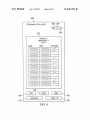
FIG. 6 illustrates a document display 200 depicting the ?rst
45
134, 136, and 138 have similar features as described in the
foregoing examples. These examples, not intended to be lim
iting, are provided to illustrate one embodiment for a main
menu display screen.
In operation, the user may install or remove a memory 50
device 30 from one of the receptacles 28. This action Will be
accompanied by a change to the memory device icon 112
corresponding to that particular receptacle 28, When the sys
tem 10 is turned on or activated. The change When a memory
device 30 is inserted into a vacant receptacle 28 on the recep
tacle card 12 may include the appearance of a line of text 120
55
102, COPY 104, PASTE 105, PRINT 106, and BACK 108
60
With an alpha numeric symbol such as the letters A, B, C, . . .
H, as shoWn in FIG. 3. Such indicating symbols may also be
used elseWhere in the system to relate the receptacle positions
to the main menu display, for example.
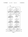
FIG. 4 illustrates a device directory display 140 depicting a
directory of contents of a selected memory device connected
to the embodiment of FIG. 1. The selected memory device,
from a selected folder, e.g., the Project A Presentation 172/
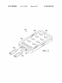
174 (See FIG. 5) of a compact memory device 30 connected
to a receptacle 28 in the receptacle card 12 of the embodiment
of FIG. 1. The page 1/4 may be indicated by the label 1/4 in
the upper right hand corner of the document display 200,
Which tracks the particular page selected by the user. Touch
ing the loWer end of the document display 200 at the location
of a button image initiates the corresponding command or
function. In some cases touching the document display 200
tWice or in tWo different locations, or dragging one’s ?nger is
required to initiate the command or function. As in screen 40
a set of command buttons for the functions MAIN MENU
indicating the identity of the memory device 30, and the
appearance of a bar graph image 114 to indicate the occupied
capacity 116 of that memory device 30. The observant reader
Will note that each memory device position may be identi?ed
page 1/4 of a selected document 202 such as anAttendee List
65
may appear at the loWer end of the document display 200.
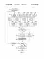
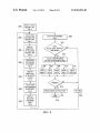
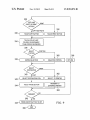
FIG. 7 illustrates a How chart for navigating a log-on dis
play to access content stored in the system 10 illustrated in
FIG. 1. The process may begin at step 220 “press the ON/OFF
button 62.” The ON/OFF button 62 may be a push on/push off
sWitch, a toggle sWitch, or a rocker sWitch supported in the
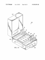
chassis 18 as shoWn in FIG. 1, or even a touch sWitch inte
grated into the touch sensitive display screen 40. When turned
ON, the system 10 displays the main menu 100 that presents