1
The control cable is used for Control, and is used to connect the LDR Link unit
to a PC with a suitable RS232 control interface for connection to the domo PC
GUI application or an embedded control application.
7.3.4
Video
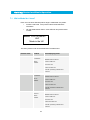
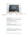
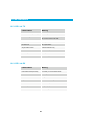
Connect the video input to the Amphenol connector labeled ‘Video In’.
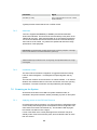
Connector
Signal
Video BNC (on cable)
75 ohm composite video source, PAL or NTSC
software selectable
Typically the video source will be a small colour or black and white CCD
camera.
7.3.5
Antennas
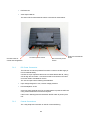
The unit is supplied with 868MHz (or 458MHz) omni-directional flexible
antennas as standard. These should be screwed directly to the panel mount
TNC RF Out connector. Care should be taken to not over tighten the
antenna. It is recommended that the transmit antenna should be connected
directly to the unit and not via a cable. Any cable in this position will reduce
the range performance of the equipment.
Important Note: The supplied antennas are dipole antennas and do not require a ground plane. Users might
wish to use other antennas, such as directional antennas for greater range.
Additional antennas may be ordered from domo. For longer range, more specialized antennas such as Yagis
can be supplied.
7.3.6
Installation notes
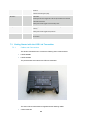
The domo LDR Link transmitter is supplied in a rugged chassis with mounting
holes for ease of integration. It is designed for simple integration into any
system.
The LDR Link transmitter can be mounted in an outdoor situation. In an
outdoor situation care should be taken to mount the unit with the connectors
pointing downwards. The cable connectors must be protected by the drip
ledge.
7.4
Getting Started with the LDR Link Receive System
7.4.1
Cables and Connections
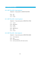
This section describes how to connect the following domo model numbers.
12