1
Technical description
Signal Path:
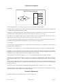
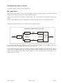
RWA-3085 Block Diagram
O/P 4
O/P 3
INPUT
SPLITTER
-7 dB
AMP
22 dB
O/P 2
O/P 1
ATTENUATOR
0 - 20 dB
MONITOR
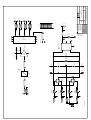
The block diagram above shows the principal parts of the signal path for the RWA-3085.
The input signal is applied directly to the input variable attenuator module which has a characteristic impedance of
75 Ohms and a maximum attenuation of 20 dB.
The BGY67A wideband RF amplifier hybrid module that follows the attenuator has a fixed gain of approximately
22 dB (maximum 24 dB) resulting in a minimum gain of 2 dB above input level at its output.
The output of the amplifier feeds a passive splitter module with five output ports. The loss at any output is
approximately 7 dB, resulting in an overall system gain of from –5 dB to + 15 dB.
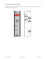
Four of the outputs are available on the rear of the amplifier and one on the front panel for monitoring purposes.
Note that this front panel output is no different to any other output in its characteristics.
Power supply:
The RWA-3085 is equipped with two AC rectifier circuits to take advantage of the redundant AC power supplies
provided in IRT’s 3 RU frames.
Filters FIL 1 to 4 and capacitors C1 to 4 provide EMC filtering between the power supply busses and the module.
Resistors F 1 to 4 provide fuse protection to the frames power supply busses in the event of a failure on the module.
Should these fail they should only be replaced by resistors of the same type and value or damage may result to the
module and may also effect the operation of other modules in the same frame.
The rectified power is filtered by capacitors C 5 to C 12 providing both high an d low frequency filtering.
The BGY67A hybrid amplifier module is the only active component in the RWA-3085. This amplifier requires a
single sided DC supply of +24 V, which is outside the range normally available from the frame’s AC power supply
buss.
In order to obtain this supply a DC-DC converter is employed. This converter may be damaged by overvoltage on
its input and so input protection is provided by the Zener diode ZD 1 and resistors R 1 & 2, which limit the input
voltage to 33 Volts.
The output of the DC-DC converter has additional filtering applied by the LC network of C 13 to 15 and L 1.
The front panel DC LED is fed from the 24 Vdc supply and thus gives a true indication of the whole power supply
operation and power being available to the amplifier module.
Internal adjustments
The RWA-3085 has no internal adjustments or user serviceable parts.
3085-rwa.ib.rev4.doc
Page 5 of 10
16/10/2007