1
LUNAIRE ENVIRONMENTAL
5.3
Chamber Drain Connections
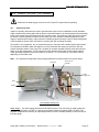
There are two different water drain connections for draining condensation from the chamber. The door trough
drain pipe runs from the bottom front of the chamber to a ¼" O.D. plastic compression fitting on the bottom
left side. The second drain line consists of a ½" copper pipe that runs out from the bottom rear of the
chamber. The connection may be piped in hard line or with a flexible hose and clamp. This line drains
condensation from the plenum, the chamber floor, and the door drip pan mounted on the bottom of the door.
5.4
Air Supply Connection (-3 & -4 Models)
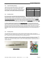
Your chamber will require a compressed air supply for the Dry Air Dehumidification / Dry Air Purge System
option. The supply should be clean and dry, and range from 80 PSIG min. to 100 PSIG max. The connection
type is ¼” FPT. Make sure the connection is secure. Reference the corresponding “Options” section in this
manual and your chamber specifications for more details.
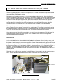
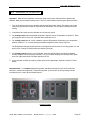
Flow Adjustments:
Twin Tower
Heatless Dryer
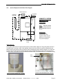
Adjust the flow adjustment valve at the supply
connection to maintain 100 PSIG max. Adjust the
flowmeter metering valve to approximately 300
cubic feet per hour.
Note: Your equipment configuration may be
slightly different from what is shown.
Flow
Adjustment
Valve
Metering
Valve
Compressed
Air Supply
Input
Dry Air Purge System
Steady State / Stability Test Chambers,
Models CEO9xx - 1,- 2,- 3,- 4: W96s
Page 12