1
(100)
Note 4
167
2.5
7
3.7
49
40
S
M
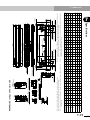
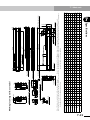
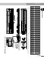
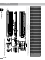
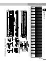
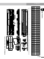
Cross-section of optional cable carrier
24
15
G
L
66
50
150
186
φ8
φ7.5
32.5
54±1
(Note 1)
155±5 (L side origin position)
(155 : When at R side origin)
105
A
200
50 ±0.02
70
190
Depth 10
D ±0.02
Bx200
Effective stroke
L
(A)
(Note 1)
54±1
(155 : When at L side origin)
155±5 (R side origin position)
6
8
8
6
6
7
7
8
8
9
9
10 10
11
11
12 12 13 13 14 14 15 15 16 16 17 17 18 18 19 19 20 20 21
10 10 12 12 14 14 16 16 18 18 20 20 22 22 24 24 26 26 28 28 30 30 32 32 34 34 36 36 38 38 40 40 42 42 44
5
Weight (kg) 9.0 10.7 12.3 13.9 15.6 17.2 18.8 20.4 22.1 23.7 25.3 27.0 28.6 30.2 31.9 33.5 35.1 36.7 38.4 40.0 41.6 43.3 44.9 46.5 48.2 49.8 51.4 53.0 54.7 56.3 57.9 59.6 61.2 62.8 64.5 66.1 67.7 69.3 71.0 72.6
6
5
4
4
200 300 400 500 600 700 800 900 1000 1100 1200 1300 1400 1500 1600 1700 1800 1900 2000 2100 2200 2300 2400 2500 2600 2700 2800 2900 3000 3100 3200 3300 3400 3500 3600 3700 3800 3900 4000 4100
4
D
3
C
3
1
2
105 55 105 55 105 55 105 55 105 55 105 55 105 55 105 55 105 55 105 55 105 55 105 55 105 55 105 55 105 55 105 55 105 55 105 55 105 55 105 55
A
B
2
410 510 610 710 810 910 1010 1110 1210 1310 1410 1510 1610 1710 1810 1910 2010 2110 2210 2310 2410 2510 2610 2710 2810 2910 3010 3110 3210 3310 3410 3510 3610 3710 3810 3910 4010 4110 4210 4310
L
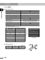
Effective stroke 100 200 300 400 500 600 700 800 900 1000 1100 1200 1300 1400 1500 1600 1700 1800 1900 2000 2100 2200 2300 2400 2500 2600 2700 2800 2900 3000 3100 3200 3300 3400 3500 3600 3700 3800 3900 4000
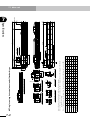
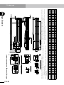
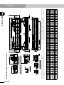
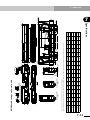
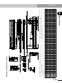
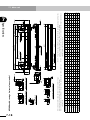
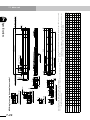
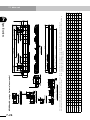
Note 3. For models with a 2,100mm or longer stroke, optional L type cable carriers can only
be used.
Note 4. For models with a 3,000mm or longer stroke and an optional L type cable carrier,
a roller is installed to prevent the cable carrier from sagging.
+0.015
2-φ10H7 0
C-M6x1.0 Depth 10
Ground terminal (M4)
+0.012
Depth 10
4-φ6H7 0
4-M6x1.0 Depth 12
Note 1. Distance from both ends to the mechanical stopper.
Note 2. The origin is set on the L side at the time of shipment. It can be changed to the R
side by parameter setting.
20.5
14
Detail of section G
7.2
4.5
Optional cable carrier L type
238
90
φ30
Diameter of roller
Optional cable carrier S / M type
240.5 (M option)
215.5 (S option)
20.5
14
80 : Top face of slider
64
14
35
29
136
120
(Between
φ6H7±0.02)
(100)
7-22
98
7
100
Specifications
MF30 single-carriage horizontal mount model
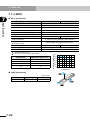
7-1 Main unit