1
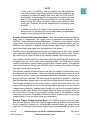
13.12.8 QADC64 Control Register 2 (QACR2)
Control register two is the mode control register for the operation of queue 2. Software
specifies the queue operating mode of queue 2, and may enable a completion and/or
a pause interrupt. All control register fields are read/write data, except the SSE2 bit,
which is readable only when the test mode is enabled. Most of the bits are typically
written once when the software initializes the QADC64, and not changed afterwards.
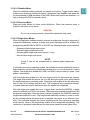
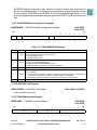
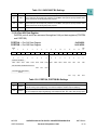
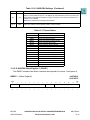
QACR2 — Control Register 2
MSB
0
1
2
CIE2
PIE2
SSE2
0
0
3
4
0x30 480E
0x30 4C0E
5
6
7
MQ2
8
9
10
11
RESUME
12
13
14
LSB
15
0
0
0
BQ2
RESET:
0
0
0
0
0
0
0
1
0
0
0
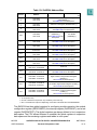
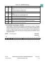
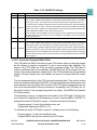
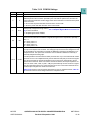
Table 13-14 QACR2 Bit Settings
Bit(s)
0
1
2
Name
Description
CIE2
Queue 2 completion interrupt enable. CIE2 enables completion interrupts for queue 2. The interrupt request is generated when the conversion is complete for the last CCW in queue 2.
0 = Queue 2 completion interrupts disabled.
1 = Generate an interrupt request after completing the last CCW in queue 2.
PIE2
Queue 2 pause interrupt enable. PIE2 enables pause interrupts for queue 2. The interrupt
request is generated when the conversion is complete for a CCW that has the pause bit set.
0 = Queue 2 pause interrupts disabled.
1 = Generate an interrupt request after completing a CCW in queue 2 which has the pause bit set.
SSE2
Queue 2 single-scan enable bit. SSE2 enables a single-scan of queue 2 after a trigger event
occurs. The SSE2 bit may be set to a one during the same write cycle that sets the MQ2 bits for
the single-scan queue operating mode. The single-scan enable bit can be written as a one or a
zero, but is always read as a zero.
The SSE2 bit allows a trigger event to initiate queue execution for any single-scan operation on
queue 2. The QADC64 clears SSE2 when the single-scan is complete.
3:7
8
9:15
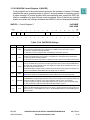
MQ2
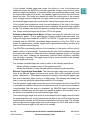
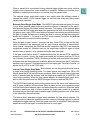
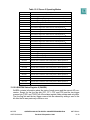
Queue 2 operating mode. The MQ2 field selects the queue operating mode for queue 2. Table
13-15 shows the bits in the MQ2 field which enable different queue 2 operating modes.
Queue 2 resume. RESUME selects the resumption point after queue 2 is suspended by queue
1. If RESUME is changed during execution of queue 2, the change is not recognized until an endRESUME of-queue condition is reached, or the queue operating mode of queue 2 is changed.
0 = After suspension, begin execution with the first CCW in queue 2 or the current sub-queue.
1 = After suspension, begin execution with the aborted CCW in queue 2.
BQ2
MPC555
USER’S MANUAL
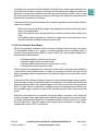
Beginning of queue 2. The BQ2 field indicates the location in the CCW table where queue 2
begins. The BQ2 field also indicates the end of queue 1 and thus creates an end-of-queue condition for queue 1. Setting BQ2 to any value ≥ 64 (0b1000000) allows the entire RAM space for
queue 1 CCWs.
QUEUED ANALOG-TO-DIGITAL CONVERTER MODULE-64
Revised 15 September 1999
MOTOROLA
13-38