1
RPF6
FILTER WHEEL
User Manual
April 2005
Copyright 2005 DTA s.r.l.
All rights reserved. The reproduction of any part of this manual is allowed only with the written
authorization by DTA s.r.l..
The contents of this manual may be subject to changes without any warning.
DTA are not responsible for errors that may occur in this manual.
Revision 1.0 dated 28/04/2005
2
-
CONTENTS
INTRODUCTION
4
INSTALLATION OF HARDWARE AND SOFTWARE
5
SOFTWARE OPERATION
6
DETAIL OF THE RPF6 CONNECTOR
9
FILTER WHEEL’S SOFTWARE MANAGEMENT
CONTROL DESCRIPTION
10
SPECIFICATIONS
13
OPTIONS
13
INDEX
14
3
INTRODUCTION
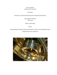
RPF6 is a motorized filter wheel, which has six different holders for filters of 1¼" diameter.
It has been designed to be driven directly from ViSTA, the DTA software that manages the cameras, but it is
also supplied with a separated control program for all Windows systems.
There are two different connection systems: by means of RS232 or by means of the parallel port.
It is possible to set the rotation speed and a different stop position for each filter.
The motor hold current is user adjustable.
This product can be customized specifying different size, number of filters, input or output adapters.
The typical applications are Photometry, Microscopy and colour sequences.
THE STANDARD SYSTEM INCLUDES:
•
•
•
•
•
•
4
assembled unit in light alloy with threaded 31.75 input
RS232/Parallel interface
2.5 m PC parallel link cable
managing software for Windows 95/98/ME
230V power supply
case, manual with test report and 24 months of warranty
-
INSTALLATION OF HARDWARE AND SOFTWARE
Hardware and software installation of this instrument is particularly simple and intuitive. You must
conform to the following steps:
1.
Insert the SDK CD, provided with the filter wheel.
2.
Copy the files RPF6.EXE and RPF6.INI in a directory.
3. Connect the feeder to the instrument and to the PC serial port (this operation must be
performed before turning on the computer).
4.
Turn on the computer and start up Windows.
5.
Feed the instrument.
6.
Now the instrument is working and it selects the first filter automatically.
7.
Start the RPF6.EXE program. Thanks to simple graphic interface it makes possible to:
• Show the serial or parallel port by which the filter wheel has been connected to the
computer
• Choose the angular velocity of the filter wheel
• Attribute a name and colour to each filter
• Calibrate the wheel
• Select each filter
5
SOFTWARE OPERATION
When you activate RPF6.EXE it will appear the following window:
yellow
blue
dark green
pastel green
blue sky
red
fig.1
If you select Port Setup from the Control menu it is possible to specify the input/output port which the filter
wheel is connected on:
fig.2
Using Start from the Control menu, RPF6 program verifies if the filter wheel connection is correct. If so, it
will appear the following window which differs from fig.1 because now buttons 1 to 6 are enabled.
6
-
fig.3
Now it is possible to choose each filter by clicking with the mouse one of the six buttons or by pressing the
function keys ‘F1’ … ‘F6’ to select filters ‘1’ … ‘6’ respectively.
On the contrary, if there are connection problems, after few seconds it will appear on the screen the error
message: RPF Don't Send ACK.
fig.4
In this case you must press OK and verify that:
1. The instrument is properly fed.
2. The serial (or parallel ) cable has been correctly connected.
3. The input/output port specified by the Port Setup control is the right one.
By means of the Filter Name control from the Control menu it is possible to associate a name and a colour to
each filter (selecting them between the possible ones on the colour palette).
7
fig.5
Once you have made these changes, let’s press OK.
If necessary, the Autozero control from the Control menu enables the instrument to autocalibrate itself (for
example if the perfect alignment of the filter on telescope axis has been lost).
Calibration from the Control menu enables to specify the steps number between one filter and the other, to
select the offset and the torque motor.
Each step is equivalent to a 1.25 degrees rotation and there are 48 steps between a filter and the other.
On the contrary, the offset enables to calibrate the alignment between the filter wheel axis on the instrument
axis.
Varying the torque, it is possible to choose the torque motor while it is not running. If the filter wheel is not
subject to particular vibrations or shoves, you can choose the Min Torque or Zero Torque function.
Otherwise, if the filter wheel is subject to vibrations, it would be better to select the value MidTorque or Max
Torque function.
Finally, in order to control the angular velocity of the filter wheel, it is sufficient to choose Speed from the
Control menu and to vary the velocity using the proper buttons.
fig.6
8
-
DETAIL OF THE RPF6 CONNECTOR
The filter wheel can be connected to the PC either by means of the serial interface or the parallel one.
Nevertheless, using the serial interface you will obtain the better connection, because it enables to use very
long connection cables .
CONNECTOR’S NUMERATION
SIGNALS ON THE CONNECTOR
PIN
1
2
3
4
SIGNAL
READY
TxD
RxD
D3
COMMENT
Parallel port Handshake
Serial Transmission
Serial Reception
Parallel Bit 3
5
6
7
8
9
GND
D2
D1
D0
VDD
Ground
Parallel Bit 2
Parallel Bit 1
Parallel Bit 0
Feed 12V 500 mA
9
FILTER WHEEL’S SOFTWARE MANAGEMENT.
It is possible to check the RPF6 filter wheel by programming the serial interface.
These are the statements to be respected:
•
•
•
•
bit-rate : 4800
no parity bit
8 characters plot
1.5 bit stop
The following controls are available:
1.
2.
3.
4.
5.
6.
7.
8.
9.
“F” < filter number > <CR>
“N” < filter number > <steps > <CR>
“R” <CR>
“E” <CR>
“V” <velocity> <CR>
“Z” <CR>
“D” <duty_cicle> <CR>
“D”<CR>
“O”<offset> <CR>
CONTROL DESCRIPTION
1. "F" < filter number > <CR>
Let suppose we want to set filter number 2; it will be enough to send:
a) character "F";
b) character "2";
c) carriage return.
(<CR> indicates carriage return, whose ascii code is 13).
After sending the control, in case of not transmission errors, the filter wheel will set the specified filter
(in our example, filter number 2) and, once the operation is concluded, it will transmit us: "ACK"<CR>.
Otherwise, if there have been transmission errors, no one operation will be implemented and it will
transmit: "NACK"<CR>.
2. "N" < filter number> <steps > <CR>
Let suppose we want to vary the steps number between filter 2 and filter 3 and increase them to 50; it is
sufficient to transmit:
a) character "N";
b) character "2";
c) a character whose ascii code is equivalent to the steps number (in this case a character whose ascii
code is 50);
d) carriage return.
10
-
Even in this case, in case of not transmission errors, the filter wheel will transmit: "ACK"<CR>.
Otherwise, no one operation will be implemented and it will transmit: "NACK"<CR>.
3. "R" <CR>
This control enables us to know the present position of the filter wheel.
Let suppose that presently it is selected filter number 3, then if we transmit:
a) character "R";
b) carriage return.
the filter wheel will transmit: "3ACK"<CR> if there have been no transmission errors, and
NACK"<CR> if there are errors.
4. "E" <CR>
This control enables us to know the firmware version.
Transmitting:
a) character "E";
b) carriage return.
the filter wheel will answer: <2 byte> "ACK"<CR>.
For example if the firmware version is 1.0, we will receive: "10ACK"<CR>.
Even in this case, if there have been transmission errors, the filter wheel will transmit "NACK" <CR>.
5. "V" <velocity> <CR>
It is possible to change the wheel angular velocity by transmitting:
a) character "V";
b) a character whose ascii code indicates the velocity (velocity range gets from 220 for high angular
velocity to 180 for low ones);
c) carriage return.
The filter wheel will transmit: "ACK"<CR> if there have been no transmission errors; "NACK"<CR>
on the contrary.
6. "Z" <CR>
If we want to have a perfect alignment between the telescope axis and each filter axis, it will be enough
to transmit:
a) character "Z";
b) carriage return.
The filter wheel will implement the alignment, if there have not been transmission errors, it wiil set filter
number 0 and will transmit "ACK"<CR>. In case of transmission errors, it will transmit "NACK"<CR>.
11
7. “O” <offset> <CR>
With this control we can choose the initial offset by which the RPF will set itself as soon as we give it
the zero setting control. The syntax is clear and the wheel answer will be:
ACK<CR>
and NACK <CR>.
8. “D” <duty – cicle > <CR>
To change the duty cycle it is sufficient to send:
a) character "D";
b) a character included within 0 and 3 (0 = void torque; 1 = minimum torque; 2 = medium torque; 3 =
maximum torque)
c) <CR>
This point the wheel will answer ACK<CR> or NACK <CR>, as in the other cases.
9. “D” <CR>
This control enables us to know the present duty cycle of the microcontroller. The answer will be:
<duty-cicle> ACK <CR> oppure NACK<CR>.
NOTE:
Between a character and the other it would be better to insert a waiting cycle of about 10 ms to enable the
RPF microcontroller to process correctly the input data.
12
-
SPECIFICATIONS
POSITIONING SPEED
0.2 s
NUMBER OF POSITIONS
6
STANDARD MOUNT
1¼’’
SPEED CONTROL
Yes
SERIAL INTERFACE
RS232 9600 Baud
PARALLEL INTERFACE
4 bit input, 1 bit output
MAXIMUM FILTER THICKNESS
8 mm
BACKFOCUS
30 mm
POWER SUPPLY
12V 500mA
DIMENSIONS
Φ 140 mm
OPTIONS
RGB-6
31.7 mm RGB interference filter kit
NIK-6
Adapter for Nikon lens
MIN-6
Adapter for 42x1 mm lens
ARH-6
Adapter for HiRes
ARI-6
Adapter for DISCOVERY, iCAM
PAR-6
Standard parallel port link cable
13
INDEX
D
DETAIL OF RPF6 CONNECTOR
9
F
FILTER WHEEL’S SOFTWARE MANAGEMENT
10
I
INTRODUCTION
INSTALLATION OF HARDWARE AND SOFTWARE
4
5
O
OPTIONS
13
S
SPECIFICATIONS
14
13
s.r.l.
Viale Campania 23
56021 Cascina (Pisa) - ITALY
web site: www.dta.it
e-mail: sales@dta.it