1
INSTALLATION GUIDE
6.9.3.
SINUS PENTA
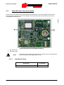
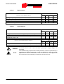
Electrical Features
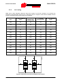
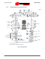
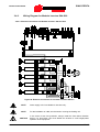
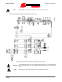
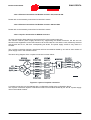
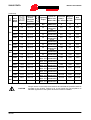
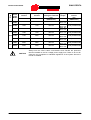
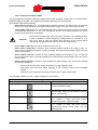
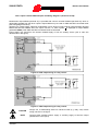
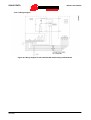
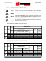
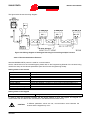
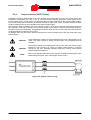
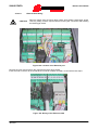
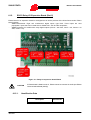
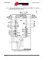
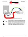
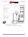
WIRING:
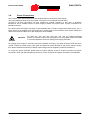
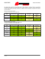
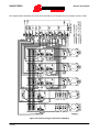
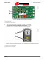
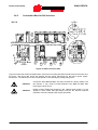
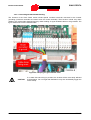
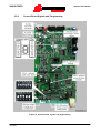
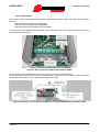
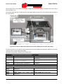
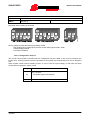
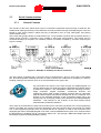
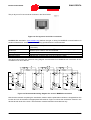
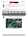
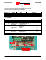
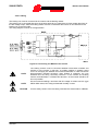
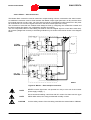
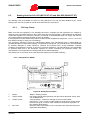
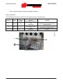
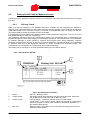
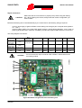
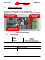
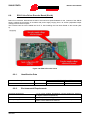
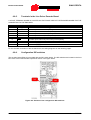
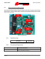
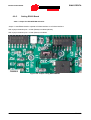
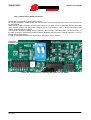
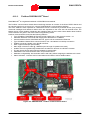
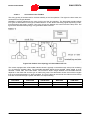
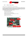
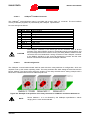
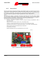
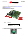
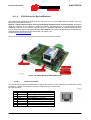
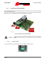
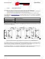
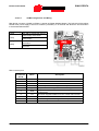
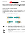
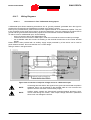
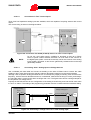
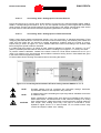
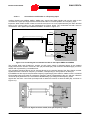
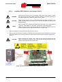
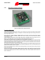
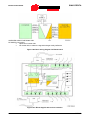
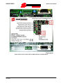
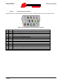
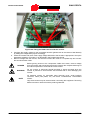
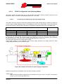
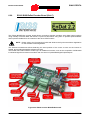
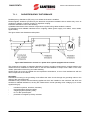
Once ES822 board is fitted, connector RS485 installed on the inverter will automatically disable. D-type, 9pole male connector (RS485) or female connector (RS232-DTE) located on ES822 board activate depending
on the position of J1.
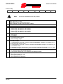
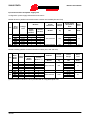
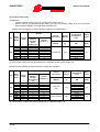
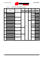
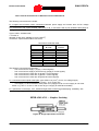
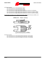
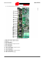
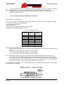
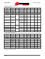
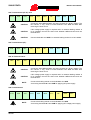
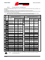
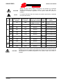
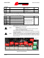
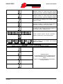
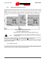
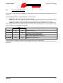
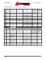
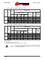
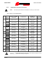
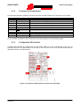
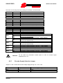
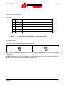
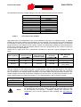
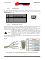
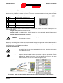
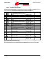
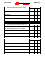
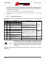
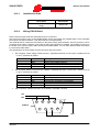
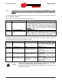
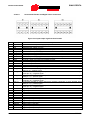
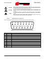
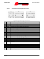
Contacts of CN3, D-type, 9-pole male connector (RS485) are as follows:
PIN
1-3
2-4
5
6-7
8
9
FUNCTION
(TX/RX A) Differential input/output A (bidirectional) according to standard RS485. Positive polarity
in respect to pins 2 – 4 for one MARK.
(TX/RX B) Differential input/output B (bidirectional) according to standard RS485. Negative polarity
in respect to pins 1 – 3 for one MARK.
(GND) control board zero volt
Not connected
(GND) control board zero volt
+5 V, max 100mA for the power supply of an auxiliary RS485/RS232 converter (if any)
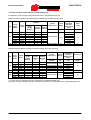
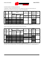
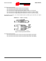
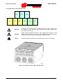
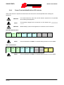
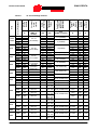
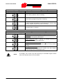
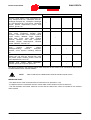
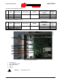
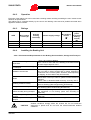
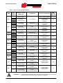
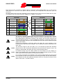
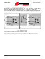
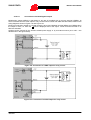
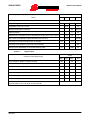
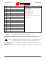
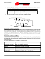
Contacts of CN2, D-type, 9-pole female connector (RS232-DCE) are as follows:
PIN
1-9
2
3
5
4-6
7-8
FUNCTION
Not connected
(TX A) Output according to standard RS232
(RX A) Input according to standard RS232
(GND) zero volt
To be connected together for loopback DTR-DSR
To be connected together for loopback RTS-CTS
289/418