1
Hytec Electronics Ltd
DIO8005/UTM/1.1
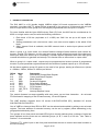
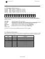
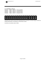
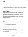
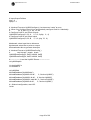
3.9 Interrupt Request Vector IRV IP (Read/Write)
Address:
Address:
Address:
Address:
Base + 0x0020 = Group A I/O = 1 to 32
Base + 0x0120 = Group B I/O = 33 to 64
Base + 0x0220 = Group C I/O = 65 to 96
Base + 0x0320 = Group D I/O = 97 to 128
Sets the interrupt request vector address for the routine to jump to when an interrupt occurs
D15
D14
D13
D12
D11
D10
D09
D08
D07
D06
D05
D04
D03
D02
D01
D00
V15
V14
V13
V12
V11
V10
V09
V08
V07
V06
V05
V04
V03
V02
V01
V00
At switch on the default value is 0Hex
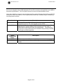
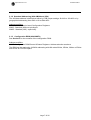
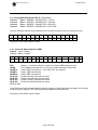
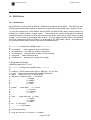
3.10 Control & Status Register (VME)
Control (Write / Read)
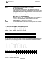
Address: Base + 0x0400
D15
D14
D13
D12
D11
D10
D09
D08
D07
D06
D05
NU
NU
NU
NU
GpD
INT
GpC
INT
GpB
INT
GpA
INT
NU
NU
NU
D04
D03
D02
D01
D00
INTSEL2 INTSEL1 INTSEL0 INTEN RST
RST
Writing ‘1’ to this bit clears the control and status VME register to zero.
INTEN
This enables interrupts from IO change of state interrupts. Active high
INTSEL0
Select VME interrupt line – 3-bit code: ‘000’ not allowed.
INTSEL1
Select VME interrupt line
INTSEL2
Select VME interrupt line
Gp A INT
Enable Group A interrupt line select.
Gp B INT
Enable Group B interrupt line select.
Gp C INT
Enable Group C interrupt line select.
Gp D INT
Enable Group D interrupt line select.
NU-Not Used
If the Group has been enabled and an interrupt (change of state) has been generated, the interrupt
vector priority is relayed, if the (INTEN) interrupt enable has also been set.
At switch on the default value is 0Hex
Page 14 of 26