1
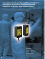
D40Z
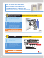
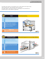
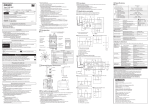
Application Examples
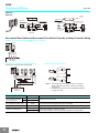
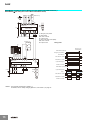
G9SP-N20S(24 VDC) (2-channel Emergency Stop Switch Inputs + Non-contact Door Switch/Manual Reset)
G9SP-N20S
V1
Si0
Si1
Si2
Si3
Si4
G1
T0
T1
T2
T3
T4
Si5
V2
So1
So0
G2
DC24V
24 VDC
KM1
-NC
11
S1
S2
21
? 12
KM2
-NC
22
KM1
KM2
S3
Black
White
Brown
Blue
Yellow
Gray
24 VDC
GND
IN
COM
PLC etc.
KM1
GND
KM2
S1: Emergency Stop Switch
S2: Non-contact Door Switch (D40Z)
S3: Reset Switch
KM1, KM2: Contactor
M1: 3-phase motor
M1
Note: 1. The PL and category that correspond to this circuit example vary depending on the program configured to the G9SP-N20S.
For details, refer to "G9SP Series User's Manual (Cat.No.Z922)".
2. For details on terminal arrangement, refer to "G9SP Series User's Manual (Cat.No.Z922)".
3. Wire auxiliary outputs correctly. Incorrect wiring may lead to a failure of the auxiliary output circuit.
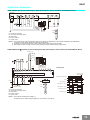
G9SX-NSA222-T03-@ (24 VDC) (2-channel Emergency Stop Switch Inputs + Non-contact Door Switch/Manual Reset)
Feedback Loop
KM1
S2
KM2
11
21
12
22
S2
Blue
Brown
Black
+24 V
White
S1
A1
T11 T12 T21 T22
Y1
Timing chart
NC NC
NC
T31 T32 T33
D1
D2
D3
D4
T41 T42
G9SX-NSA222-T03
AND
Control circuit
A2
S14 S24
ES1 ES2
L1
X1
Emergency stop
switch operation
OFF
Emergency stop switch S1
X2
D40Z
PLC etc.
24 VDC
KM1 KM2
S14
Motor controller
Reset switch S3
–
KM1, KM2 N.C. contact
KM1
GND
Motor controller
(Operation command)
S1: Emergency Stop Switch
S2: Non-contact Door Switch (D40Z)
S3: Reset Switch
KM1, KM2: Contactor
M1: 3-phase motor
KM1, KM2 N.O. contact
KM2
Operation command
Rotation of motor
M1
OFF-delay time
OFF-delay time
Note: 1. The example corresponds to category 4.
For details, refer to “Safety Category (EN 954-1, ISO 13849-1)” on page 16.
12