1
SESAM
Program version 3.0
3.1.8
Submod
01-NOV-2004
3-3
Coordinate Tolerance
Node-to-Node Coupling
The coordinate tolerance for node matching must be given in the same unit as used by the global and submodel structures. The tolerance is the maximum allowable distance between a driven node in the sub-model
and a node in the global model.
Node-to-Element Coupling
For node-to-element coupling the coordinate tolerance is how far away a node in the sub-model may be
from an element in the global model and still be taken as being inside the element. But the use is a little bit
different from the use of the coordinate tolerance in the node-to-node coupling. For node-to-element coupling the coordinate tolerance is transformed to a relative tolerance for each element searched through in the
global model. This relative tolerance is calculated as the specified coordinate tolerance divided by the diagonal in a bounding box around each element in the global model. The consequence of this is that the actual
tolerance is much smaller out-of-plane than in-plane for most shell elements (in-plane dimensions are usually much larger than the thickness). This method with calculation of a relative tolerance will only map the
user’s tolerance exactly for a cube with sides parallel to the x-, y- and z-coordinate axes.
3.2
Steps in use of Submod
Independent analyses are performed on the global model and on the sub-model. The only link is the transfer
of displacement values for the driven variables.
3.2.1
Creation of a Global Model Results File
The user runs a ’global’ model calculation through Sestra, the linear Finite Element Method program, and
obtains a Results Interface File for this model. If the user then wants to:
• Study detailed stresses and displacements in a specific area of this model,
• Model some detail differently or more accurately,
• Model some detailswith solid elements instead of shell elements,
he may create a separate model for this part as described below.
3.2.2
Creation of a Sub-Model
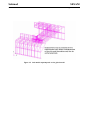
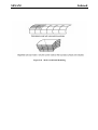
By using GeniE, Patran-Pre, Prefem and/or Presel or a similar program, a sub-model of a part of the global
model may be created. This sub-model may consist of one or more superelements and the part of the global
model may be chosen without considering where the superelement boundaries are in the global model. The
boundaries of the sub-model to be given displacements taken from the results of the global model, have to
be given prescribed displacements type of boundary condition in the first level superelements of the submodel. These prescribed displacements will later be transferred from the results file of the global model.
The coordinates of the boundaries of the sub-model must have the same coordinates as the same positions in
the global model. The ’coordinates’ are in this context the coordinates in the highest level superelement of