1
Host HS Test Procedure for YOKOGAWA DL9240/DL9240L/DL6154
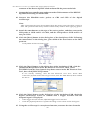
connector of the Device SQ TEST block and turn ON the power to the hub.
9.
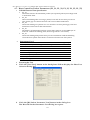
Connect the host controller port under test to the CN34 connector of the DEVICE
SQ TEST block using a 1 m USB cable.
10. Connect the PBA2500 active probes to CH2 and CH3 of the digital
oscilloscope.
Note:
After connecting the probe, heat emitted from the probe causes the offset voltage to
drift. The probe should nearly stabilize about thirty minutes after applying power.
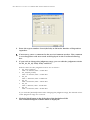
11. Attach the attachments on the tips of the active probes, and then connect the
CH2 probe to GND and D- of CN32, and the CH3 probe to GND and D+ of
test pin CN32.
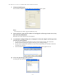
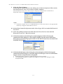
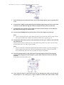
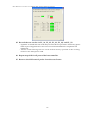
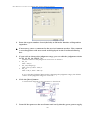
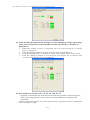
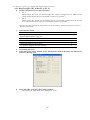
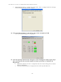
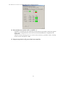
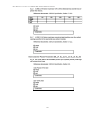
12. Click the [Next] button in the dialog box of the busXplorer-USB. Following
the instructions in the dialog box, place SW8 of the test fixture to the INIT
position.
Verify LED2 of the test fixture is lit.
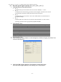
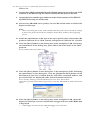
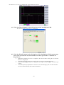
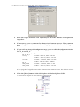
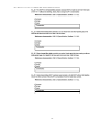
13. Click the [Next] button in the dialog box of the busXplorer-USB, click the
[Enumerate Bus] button in the HS Electrical Test Tool .Then, select
SUSPEND from the Port Control drop down menu in the HS Electrical Test
Tool, then click [EXECUTE] button .
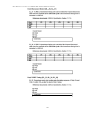
If not already running, start the HS Electrical Test Tool. Select Host
Controller/System under Select Type of Test, click the TEST button, then confirm
the above.
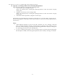
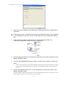
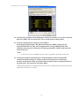
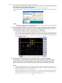
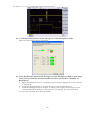
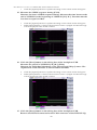
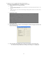
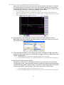
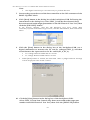
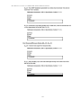
14. Click the [Next] button in the dialog box of the busXplorer-USB, check the
digital oscilloscope screen to confirm that a trigger activates and the
Suspend signal is displayed.
•
•
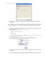
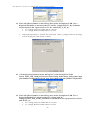
If the trigger does not activate, adjust the trigger level as needed
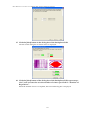
Click the [Update] button to update the image of waveform in the dialog box.
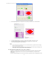
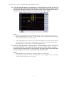
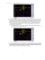
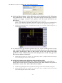
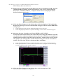
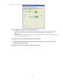
15. Using the oscilloscope’s cursor/zoom function, measure the time from the
38