1
Installation
2.5 Pre-Power Checks
Complete the following checks BEFORE
applying power to the LightMaster controller.
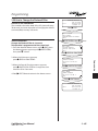
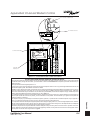
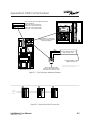
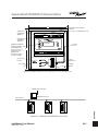
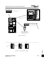
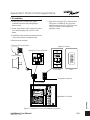
2.5.2 Verify Controller’s Supply Voltage
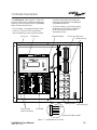
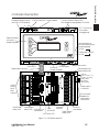
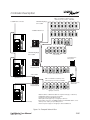
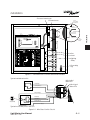
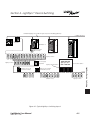
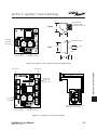
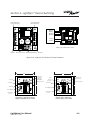
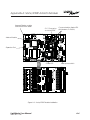
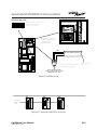
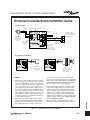
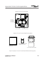
Verify that there is 24 VAC on processor and
I/O transformers secondaries and 12 VAC
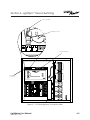
between each leg and the center tap. (See
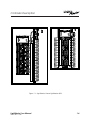
Figure 1.2.)
2.5.3 Double-Check Connections
1. Verify integrity of I/O connections.
2. Verify integrity of all internal and external
wire/cabling.
2.5.4 External Monitoring and Control
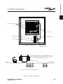
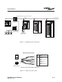
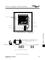
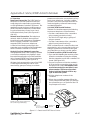
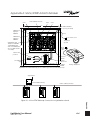
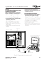
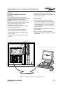
If control of the LightMaster via a PC is
desired, consult Appendix B, or C for
instructions regarding the approriate port
(on-board modem, RS 232). If controlling
via on-board modem, a telephone cord
should be used to connect to the telephone
network that is compliant to FCC part 68
rules and regulations.
2.6 Power-Up and Check Out
Complete the following procedures to powerup and checkout the LightMaster controller.
2.6.1 Power-Up the Controller
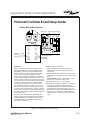
1. Turn the power switch located on each
controller CPU board ON. (See Figure 1.2.)
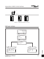
NOTE: Power-up the Node 01 Controller last.
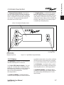
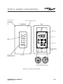
2. Verify that the controller keypad screen
displays the default time and date.
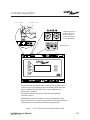
3. Verify that both power lights on each I/O
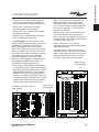
board are lit. (See Figure 1.2.)
LightMaster User Manual
Version 2E-N 1/1/05
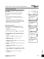
2.6.3 Perform Initial Programming
Procedures from the Main Controller Keypad
(See Section 3.)
NOTE: Conduct all programming operations
from the Master Controller.
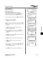
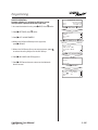
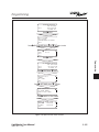
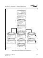
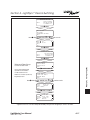
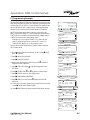
1. Clear memory: From the home screen, press
EDIT, then EDIT SYSTEM. Scroll down until
SPECIAL FUNCTIONS appears. In the SPECIAL
FUNCTIONS menu press the up and down
arrows at the same time for 5 seconds to
clear memory in the entire network.
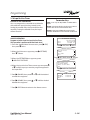
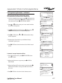
2. Set the correct date and time on the
master controller. (See Section 3.11.)
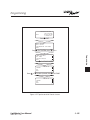
3. Verify that the network is operational by
accessing each controller node, determining its type (number of I/O points) and
turning a relay in each node ON and OFF
from the Master Controller Keypad (See
Section 3).
4. Program the switch inputs and timers.
2.6.4 Verify the Switching Function
1. Operate each switch.
2. Verify that each switch controls the
correct lighting relays in the manner you
have programmed.
2.6.5 Verify the Timer Functions
1. Temporarily adjust the Master Controller
clock and verify that the relays respond to
the timers as programmed.
2. Reset the Master Controller clock to the
correct date and time.
2-5
Installation
2.5.1 Check Controller Power Input
1. Verify that the controller power switch is OFF.
2. After verifying that the processor and I/O
transformers source voltage is 120 or 277
VAC (whichever is appropriate), power-up
the circuit.
3. Verify correct line voltage on the
primary of the transformer.
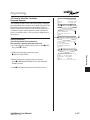
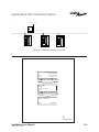
2.6.2 Verify the Lighting Relays
Switch each relay ON and OFF, pushing the
override switches located on the I/O
board(s). There are separate ON and OFF
switches for each lighting relay. (See Figure
1.2.) Verify that the relay status LED goes
ON and OFF and that the relay itself
changes state. Verify that the relay controls
the proper circuit.