1
BIOS
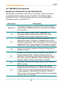
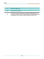
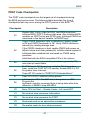
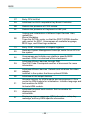
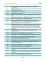
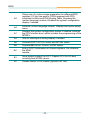
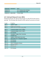
While control is in the different functions, additional checkpoints are output
to port 80h as a word value to identify the routines under execution. The
low byte value indicates the main POST Code Checkpoint. The high byte is
divided into two nibbles and contains two fields. The details of the high byte
of these checkpoints are as follows:
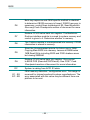
HIGH BYTE XY
The upper nibble “X” indicates the function number that is being executed.
“X” can be from 0 to 7.
0 = func#0, disable all devices on the BUS concerned.
2 = func#2, output device initialization on the BUS concerned.
3 = func#3, input device initialization on the BUS concerned.
4 = func#4, IPL device initialization on the BUS concerned.
5 = func#5, general device initialization on the BUS concerned.
6 = func#6, error reporting for the BUS concerned.
7 = func#7, add-on ROM initialization for all BUSes.
8 = func#8, BBS ROM initialization for all BUSes.
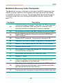
The lower nibble 'Y' indicates the BUS on which the different routines are
being executed. 'Y' can be from 0 to 5.
0 = Generic DIM (Device Initialization Manager).
1 = On-board System devices.
2 = ISA devices.
3 = EISA devices.
4 = ISA PnP devices.
5 = PCI devices.
- 72 -