1
Read These Warnings continued
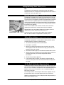
Frost Protection
If this appliance is located where the ambient air temperature could fall below 5ºC when the heater is not in use, do not
turn off the appliance electrically. This safeguard does not offer the same protection to the connecting pipework and
fittings.
Installation Environment Considerations
This unit is intended for indoor use only and should never be installed outdoors or exposed to the elements of nature.
This unit must not be positioned in an area that may be cleaned by a water jet. This unit must not be cleaned by a water
jet.
NOTE:
Zip HydroTaps are designed to operate within 1ºC to 2ºC of boiling point and at 5ºC to 10ºC for chilled drinking water.
Domestic models covered by these instructions
Model
Height mm
(inch)
Depth
mm
(inch)
Width
mm
(inch)
Weight empty kg's
lbs
Weight full kg's
lbs
30009
334 (13.2)
320 (12.5)
188 (7.4)
9 (19.8)
11.5 (25.3)
35676; 37697
353 (13.8)
388 (15.3)
290 (11.4)
9.5 (20.9)
12 (26.4)
37677
337 (13.2)
430 (16.9)
440 (17.3)
28 (61.7)
35.0 (77.1)
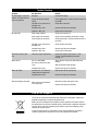
Commercial models covered by these instructions
Note: The Cup measurement =167mls, the Glass measurement = 200mls
BC 100 125
Model
Cups of
Glasses of
Boiling Water Chilled Water
per Hour
per Hour
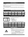
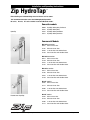
These Installation Instructions cover the entire HydroTap range. Use the chart
on the left to identify the model you are using:
Commercial Models:
BC = Boiling and Chilled, Filtered,
BF = Boiling, Filtered
BD = Boiling and Ambient Filtered
B = Boiling only (unfiltered)
D = Disabled lever controls, (optional order only- models listed on P1)
Model
Height mm
(inch)
Depth
mm
(inch)
Width
mm
(inch)
Weight empty kg's
lbs
Weight full kg's
lbs
BC60/85
337 (13.2)
430 (16.9)
440 (17.3)
28 (61.7)
34.5 (76)
BC100/125
BC150/175
B100F
B150F
337 (13.2)
395 (15.5)
353 (13.8)
409 (16.1)
430 (16.9)
465 (18.3)
323 (12.7)
340 (13.3)
440 (17.3)
500 (19.6)
290 (11.4)
321 (12.6)
28 (61.7)
29.5 (65)
9.5 (20.9)
10.0 (22.0)
35 (77.1)
38 (83.7)
12 (26.4)
14.0 (30.8)
Installation Requirements
Before installing ensure that the following have been provided at the
installation site:
• Sufficient space in the cupboard to install the undersink unit in accordance
with these Installation Instructions. A table of dimensions is given above.
NOTE: Add 65mm to the Depth of the undersink unit to allow for Water
and Electrical connections.
• A water supply connection with isolating valve inside the cupboard within
reach of the 750 mm flexible connection and positioned so that the
connection point and the stop cock will not be obstructed when the
undersink unit is installed.
Page 4 of 20
Zip Hydro Tap Installation and Operating Instructions - 81467 -