1
Advanced Energy® AE 500 Inverter
◦ Consult the facility IT administrator for network device installation support
and coordination
◦ Install the Modbus network communications cabling
• Modbus network configuration: This step can be done onsite or remotely and
should be completed by the Modbus network programmer
◦ Set the IP address assigned to the inverter and port 502 for Modbus TCP
◦ Configure the point maps for the slave devices
Modbus TCP Installation
Disconnect the power to the inverter before starting the installation.
DANGER:
Risk of electrical shock. High voltages are present in the inverter cabinet.
Both AC and DC disconnects must be in the OFF position when working on
the unit. Wait five minutes to discharge high voltage before opening the front
panels of the inverter.
DANGER:
Risque d’électrocution. L’intérieur de l’onduleur est soumis à des hautes
tensions. Les interrupteurs de courant alternatif et continu doivent être mis
HORS TENSION durant les travaux sur l’unité. Attendez cinq minutes afin de
permettre la décharge du courant haute tension avant de démonter les
panneaux avant de l’onduleur.
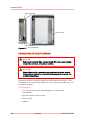
TO INSTALL THE MODBUS TCP CABLE
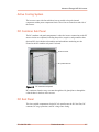
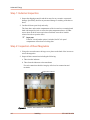
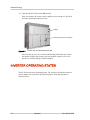
1. Remove the data monitoring gland plate on the left side of the inverter.
The data monitoring gland plate is a flat piece of metal covering the side entry
port to the inverter’s data monitoring compartment.
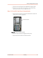
2. Cut a hole in the desired location to allow access for the cable.
3. Install a water-tight conduit hub connection.
4. Replace the gland plate.
5. Route an Ethernet cable from a network port in the facility that has been
approved by the network administrator through the conduit hub.
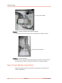
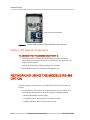
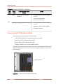
6. Connect the Ethernet cable to the Ethernet port on the communication interface
PCB.
The communication interface PCB is located in the data monitoring section in
the left upper compartment of the inverter.
570-1001791-05A
Data Monitoring and Controls
6‑5