1
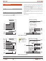
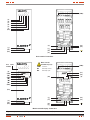
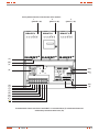
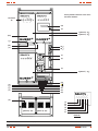
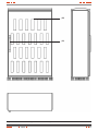
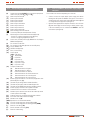
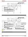
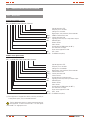
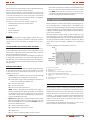
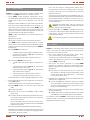
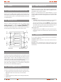
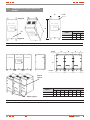
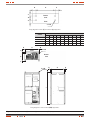
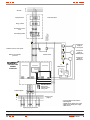
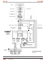
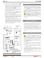
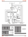
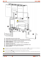
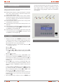
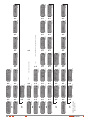
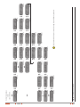
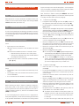
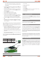
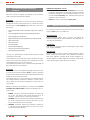
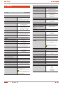
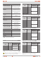
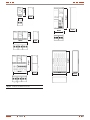
3. PresentaTIOn. 3.1. viEws and legends. 3.1.1Views of all formats of the equipment. S COM MU NIC ATIO NS LO CA LB Y PA SS LO CA LS AV ING S TA TU S PA S AR AL BY M Figures 2 and 3 show the views of (OEM) format, figures 4 and 5 the indoor one (T) and 6 the outdoor one (I). The figures only show all the connecting and manoeuvring parts that the fitter and/or user should know and/or manoeuvre for its correct installation, commissioning and operating (start up, shutdown, Manual Bypass operating, ...). Regarding the views of ILUEST+ in outdoor format (I), see figure 4 for horizontal indoor format (4), because the outdoor format (I) has an indoor format (T) basically, which is inside of an enclosure with IP54 protection degree. For furthermore details regarding of the modules views see figures 2 and 3. Regarding the legends related with the numbering of all figures see next section 3.1.2. (SW1) (a) (b) (c) (d) (e) (f) (Tm) ( ) (15) (16) (t2) (Ps) (Cb) (2U) (2N) (1R) (1N) (t2) (Ps) (Cb) COM Note over the terminal strip (17). COM. Common NC Normally closed NO Normally open (9a) (SW1) (17) (18) (9) COM. NC NO S S TA TU M AR PA S BY (Tm) (9) (LCD) () (ENT) () () () (ESC) AL S See basic module COM MU NIC ATIO NS LO CA LB Y PA SS LO CA LS AV ING Basic module. Format No 1. ( ) (15) (16) (2U) (2N) (1R) (1N) Module with LCD. Format No 1. Fig. 2. Single phase views in (OEM) format No 1 with and without front cover (Tm). 6 USER MANUAL