1
Installation & Operations Manual
CR25M Cable Beam Barrier
9
2. INSTALLATION
NOTE:
Failure to install your barrier properly could cause damage to the operating
mechanism.
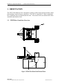
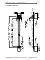
1. Read the instructions and review the project submittal drawings thoroughly. If you do not
understand any part of these instructions, please contact the manufacturer.
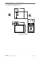
2. Set foundation as outlined in the project submittal package.
3. Check the anchor bolt locations and prepare the foundation for the barrier. Information on
anchor bolt locations can be obtained from the project submittal package.
4. Set the barrier operator and be sure to seal the bottom with duct seal. Housing must be level.
Anchor bolts must be tightened evenly.
5. Remove side arm tube cover plate. Locate pillow block bearings. Do not tighten set screws.
Now center assembly with housing. When assembly is correctly centered, tighten bearing set
screws.
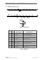
6. Insert arm, with end lock intact, into the main arm tube base. Push tube far enough to make
the cable connections at the pivot. After cables have been securely bolted to the pivot
mechanism, extend arm so that the end lock saddles satisfactorily over the anchor assembly
(on the bollard). Slide lock collar into place and tighten allen bolts.
NOTE:
If end lock fails to line up properly, loosen pillow block bearing bolts and rotate
laterally. Re-tighten bolts. Now tighten arm base bolts securely. Replace side
arm tube cover plate (tighten bolts securely).
7. With the arm in the down position, install the allotted amount of counterweights on the side
arm tube assembly. Tighten bolts securely.
8. With the barrier in the lowered position, check end lock mechanism for any type of hindrance
with bollard post and adjust accordingly if required.
9. Install and adjust the turnbuckles. Turnbuckles should be snug. DO NOT over tighten as
you can warp the gate arm.
2.1 Field Balancing Instructions -CR25 Barriers
IMPORTANT: EVERY BARRIER IS BALANCED AT THE FACTORY BEFORE IT IS
SHIPPED. IF ANY ADDITIONS OR CHANGES ARE MADE TO THE BARRIER ARM IN THE
FIELD, THE BARRIER MAY REQUIRE RE-BALANCING. AN UNBALANCED ARM MAY
DAMAGE THE OPERATOR.
If any additions or changes are made to the barrier, the following guidelines will help you
determine what changes, if any, need to be made to the barrier balance:
1. Make the desired changes to the barrier arm.
2. Secure the tip end of the arm to prevent injury or accident.
B&B ARMR
A Division of B&B Roadway and Security Solutions
0M25-9001 Rev D2