1
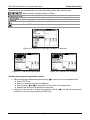
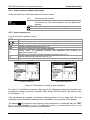
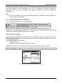
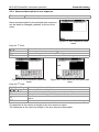
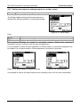
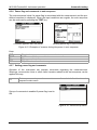
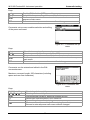
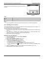
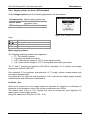
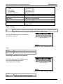
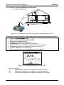
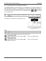
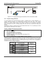
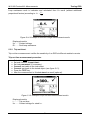
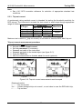
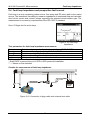
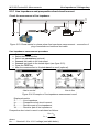
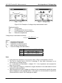
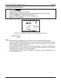
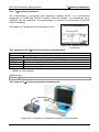
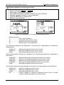
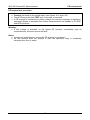
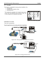
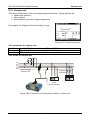
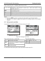
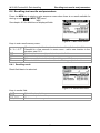
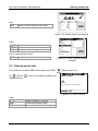
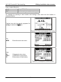
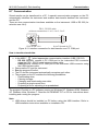
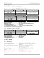
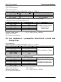
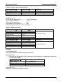
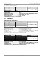
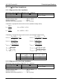
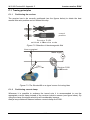
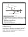
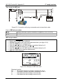
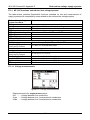
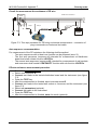
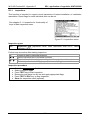
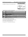
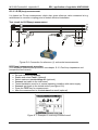
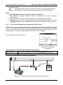
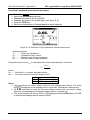
2 line/loop impedance MI 3105 EurotestXA: Measurements 2 line/loop impedance measuring procedure Connect Impedance adapter to the instrument (see figure 5.49). Select the functions Z-LINE or Z-LOOP. Enable and set limit value (optional). Power ON the Impedance adapter (ON/OFF key, green LED lits). Connect Impedance adapter to tested installation. Press the TEST key for measurement. Store the result (optional). Figure 5.50: Example of 2 line/loop measurement results Displayed results: Z ........................ Line / loop impedance, ISC ...................... Prospective short-circuit current, R........................ Resistive part of line impedance, Xl ....................... Reactive part of line impedance. The following parameters are displayed in sub-screen for single-phase line impedance measurement: IscMaxL-N ......... Maximum prospective short-circuit current. IscMinL-N .......... Minimum prospective short-circuit current. IscStd ................ Standard prospective short-circuit current. When testing phase-to-phase line impedance the following parameters are displayed in sub-screen: IscMax3Ph......... Maximum three-phase prospective short-circuit current. IscMin3Ph.......... Minimum three-phase prospective short-circuit current. IscMax2Ph......... Maximum two-phase prospective short-circuit current. IscMin2Ph.......... Minimum two-phase prospective short-circuit current. IscStd ................ Standard prospective short-circuit current. The following parameters are displayed in sub-screen for loop impedance measurement: IscMaxL-Pe ....... Maximum prospective fault current. IscMinL-Pe ........ Minimum prospective fault current. IscStd ................ Standard prospective fault current. Ub...................... Contact voltage at maximum prospective fault current (Contact voltage is measured against probe S terminal). 76