1
the system, higher orders of vibrations from the motor were exciting the eigenmodes
at higher frequencies. This should have been visible in the RMS results however the
general noise was “blurring” the response.
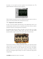
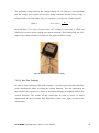
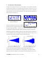
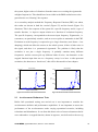
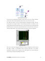
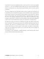
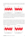
As a secondary analysis method the Frequency Response Function (FRF) was taken,
the results are shown in both the vertical (Figure 55) and the lateral (Figure 56)
directions. This is the response of the system for a specific frequency and is a type of
transfer function, i.e. input to output relation as a function of excitation frequency.
The specific frequency corresponded to the motor input frequency. Eigenmodes, i.e.
resonances, are particularly sensitive, and are seen as spikes or mountains in the FRF.
Excitation at such frequency is expected to give large vibrations (steel frame = low
damping), which can affect the sensors or the whole system, if there is little noise in
the signal, and there is a pronounced eigenmode. The problem is likely that the
excitation is not just a single frequency. It probably contains many different
frequencies, and the sensors pick up different kinds of noise. An alternative to the
stepped function input that acts as a frequency sweep is to have a wide-spectrum
excitation, also known as a “knock test”, this will be discussed in a later chapter.
2.5
x 10
Vertical at hub
-3
Lateral at hub
0.02
2
0.015
H((f))
H((f))
1.5
0.01
1
0.005
0.5
0
0
200
600
400
Angular Velocity (RPM)
0
0
800
Figure 55: Processed vertical acceleration data
200
400
600
Angular Velocity (RPM)
800
Figure 56: Processed lateral acceleration data
9.1 Accelerometer Robustness Tests
Before full operational testing was carried out it was important to consider the
accelerometers abilities and performance capabilities. It was important to assess the
performance of the accelerometers under varying operational scenarios, including
relocations and disturbances. It was from this that a series of sensor robustness checks
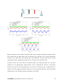
were undertaken. A stepped function, shown in Figure 57, was delivered to the test rig
CHALMERS, Applied Mechanics, Master’s Thesis 2014:36
42