1
INDICATORS AND TEST POINTS FOR LP-OT-8 TO LP-OT-15
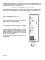
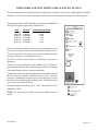
The laser transmitter has front panel test points for optical power and laser current. Only a high impedance voltmeter
should be used. The meter common should be connected to the module ground test point, not to chassis ground.
The optical power alarm LED is normally green. It turns red on insufficient
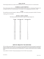
optical power. Optical ouput reads as shown below:
UNIT
LP-OT-08
LP-OT-09
LP-OT-10
LP-OT-12
LP-OT-14
LP-OT-15
OUTPUT
6.30mW
7.94mW
10.00mW
15.70mW
25.00mW
31.20mW
TEST POINT VOLTAGE
0.63V
0.79V
1.00V
1.57V
2.5V
3.12V
The laser current alarm LED is normally green. It turns red on excessive
laser current. At a typical laser current of 50mA the TP will read 1.0V.
The cooler alarm LED is normally green. It turns red when the cooler
cannot keep the laser at a constant temperature.
The RF level adjust control allows for a 4dB range of input level
adjustment.
The RF test point is calibrated to read +10dBmV @ 547.25MHz for
proper laser modulation with 83 channel loading. This level will change
with channel loading. It does not require termination.
Push the laser enable switch with an alignment tool to enable or disable
the laser. The laser should be disabled whenever there is no fiber
connected. Disabling the laser will cause a local optical power alarm,
but will not cause a remote module or chassis alarm. ‘Teasing’ this switch
may cause very brief remote alarms.
The optical output connector is type SC/APC, with optional FC/APC
connector available.
NOTE: The Laser Enable switch is no longer available on newer
models.
025-370403x11
Page 8 of 11