1
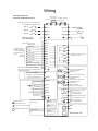
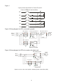
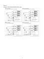
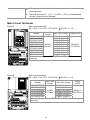
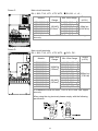
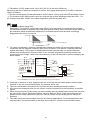
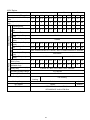
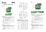
Figure 3
For frame G and f rame H
* Provide both 1-phase and 3-phase
input power
Fuse/NFB(No Fuse Breaker)
R1
L1
+1/DC+
L2
S1
V(T2)
L3
T1
-/DCU(T 1)
W(T 3)
Motor
IM
3~
L12
R2
L22
S2
L32
T2
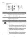
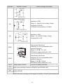
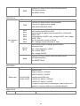
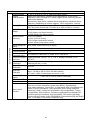
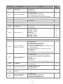
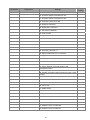
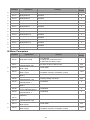
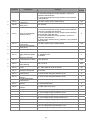
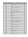
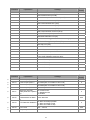
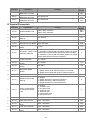
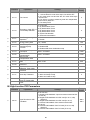
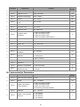
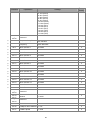
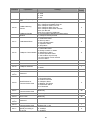
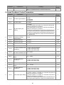
Terminals
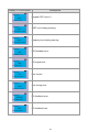
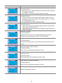
Descriptions
R/L1, S/L2, T/L3
AC line input terminals (1-phase/3-phase)
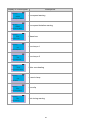
U/T1, V/T2, W/T3
AC drive output terminals for connecting 3-phase induction motor
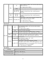
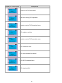
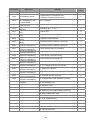
+1, +2
Connections for DC reactor to improve the power factor. It needs to
remove the jumper for installation.
(for 230V models: ≧30kW, built-in DC reactor)
(for 460V models: ≧37kW, built-in DC reactor)
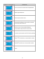
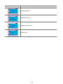
B1, B2
Connections for brake resistor (optional)
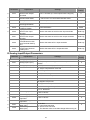
+, E
Connections for brake unit (VFDB series)
(for 230V models: ≦22kW, built-in brake unit)
(for 460V models: ≦30kW, built-in brake unit)
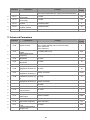
Earth connection, please comply with local regulations.
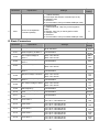
Main power terminals
;
;
;
;
;
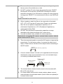
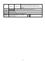
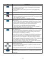
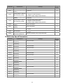
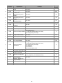
Do not connect 3-phase models to an 1-phase power source. It is
unnecessary to consider phase-sequence for these terminals R/L1,
S/L2 and T/L3.
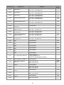
It is recommended to add a magnetic contactor(MC) in the power
input wiring to cut off power quickly and reduce malfunction when
activating the protection function of the AC motor drive. Both ends
of the MC should have an R-C surge absorber.
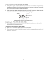
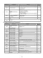
Please make sure to fasten the screw of the main circuit terminals
to prevent sparks which is made by the loose screws due to
vibration.
Please use voltage and current within the specification.
When using a general GFCI (Ground Fault Circuit Interrupter),
select a current sensor with sensitivity of 200mA or above and not
less than 0.1-second operation time to avoid nuisance tripping.
11