1
PE0401 Evaluation Kit
3.2
PE0401
Without PE0002
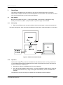
As an alternative to using the PE0002 controller kit, users may control the CMX704x target device
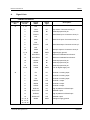
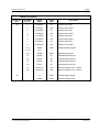
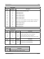
with a user-supplied host controller card. C-BUS connections are made via connector J1.
The power-up or boot state of the CMX704x is set via the connector, J1, pins 13 and 14. Consult
the relevant CMX704x documentation for valid boot modes. By default, 220kΩ pullup resistors on
the PE0401 board provide a ‘1’ state on each of the two BOOTEN pins.
A FI for the CMX704x device must be either included in the customer’s host system and loaded
into the CMX704x device on power-up or programmed into the on-board Flash memory following
TM
the guidelines in the application note: ‘Writing a Function Image to Serial Memory’.
© 2008 CML Microsystems Plc
6
UM0401/4