1
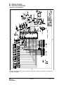
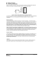
Software development using the IDE
CC1010
EM
PC running Keil
compiler and
Chipcon IDE
CC1010
Evaulation Board
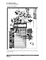
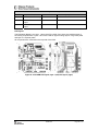
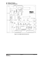
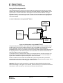
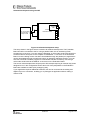
Figure 13: Software development setup
The setup shown in the figure above is suited to all software development. The Evaluation
Board should be connected to the PC using a parallel cable, this is used during Flash
programming of the chip. If you are using the debugger, a null-modem serial cable should be
connected from a serial port on the computer to the SERIAL 1 connector on the Evaluation
Board. Once the debug monitor has been downloaded through the parallel port, applications
can be downloaded through the serial port simply by starting a debugging session. You can
also use a terminal emulation program to communicate with the CC1010 by connecting a
null-modem serial cable to the SERIAL 0 connector on the Evaluation Board.
The source code examples have all (except the SPI example requiring an external chip) been
designed to run in the configuration shown above. All of the peripherals on the Evaluation
Board are available to make quick prototyping easy.
If your application requires additional hardware, this can be connected to the analog and
digital I/O pin-row connectors, enabling you to prototype an application without making a
custom PCB.
SWRU055
Page 37 of 40