1
FX3G/FX3U/FX3UC PLC User's Manual - Positioning Control Edition
6 Mechanical Zero Return (DSZR/ZRN Instruction)
Built-in Positioning Functions
6.2 DOG Search Zero Return (DSZR Instruction)
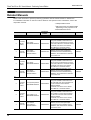
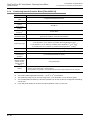
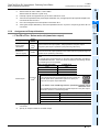
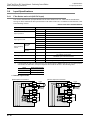
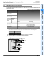
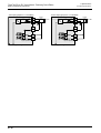
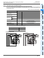
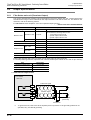
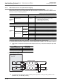
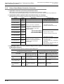
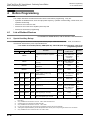
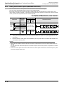
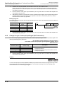
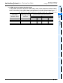
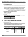
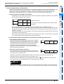
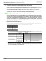
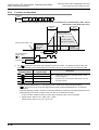
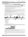
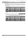
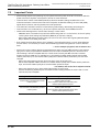
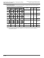
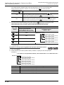
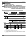
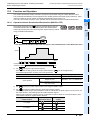
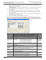
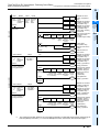
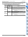
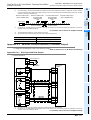
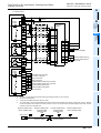
6) CLEAR signal output
This instruction can output the CLEAR signal after stopping at the origin.
If it is necessary to output the CLEAR signal at the completion of zero return, turn on the "CLEAR signal
output function enable" relay (see the following table).
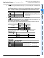
Use an FX3U/FX3UC PLC Ver.2.20 or later or FX3G PLC to specify the CLEAR signal output device.
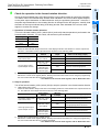
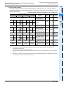
a) If it is not necessary to use the CLEAR signal device specification function, or if an FX3UC PLC below
Ver.2.20 is used.
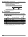
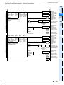
Pulse output
destination device
*1.
Status of "CLEAR
signal output function
enable" relay
Status of "CLEAR signal
device specification function
*1
enable" relay
CLEAR signal device
number
D1
= Y000
M8341=ON
M8464=OFF
Y004
D1
= Y001
M8351=ON
M8465=OFF
Y005
D1
= Y002
M8361=ON
M8466=OFF
Y006
D1
= Y003
M8371=ON
M8467=OFF
Y007
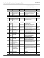
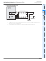
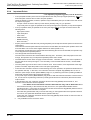
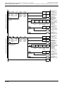
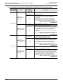
Use an FX3U/FX3UC PLC Ver.2.20 or later or FX3G PLC to use the "CLEAR signal device specification function
enable" relay.
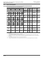
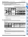
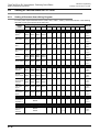
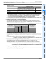
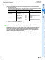
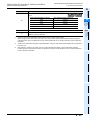
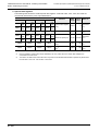
b) If it is necessary to use the CLEAR signal device specification
function:
Turn on the "CLEAR signal device specification function enable"
relay to specify the CLEAR signal output device (output Y) for the pulse output destination device
using the CLEAR signal device specification register.
→ For an example program, refer to Subsection 4.3.4 or Subsection 4.5.1.
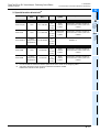
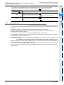
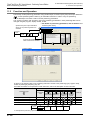
Pulse output
destination device
Status of "CLEAR
signal output function
enable" relay
Status of "CLEAR signal
device specification function
enable" relay*1
CLEAR signal device
specification register
D1
= Y000
M8341=ON
M8464=ON
D 8464
D1
= Y001
M8351=ON
M8465=ON
D 8465
D1
= Y002
M8361=ON
M8466=ON
D 8466
D1
= Y003
M8371=ON
M8467=ON
D 8467
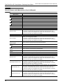
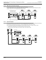
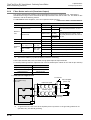
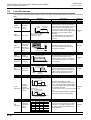
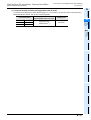
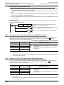
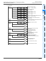
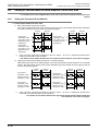
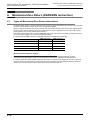
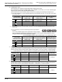
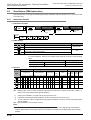
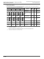
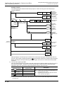
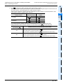
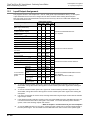
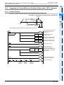
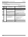
7) Zero return speed
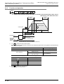
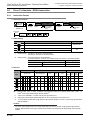
Use the devices shown in the following table to set the zero return speed. Be sure to set the zero return
speed so that the relation with the other speeds is "bias speed ≤ zero return speed ≤ maximum speed".
- If "zero return speed > maximum speed", the operation will be performed at the maximum speed.
Pulse output
destination device
Bias speed
Zero return speed
Maximum speed
D1
= Y000
D8342
D8347,D8346
D8344,D8343
D1
= Y001
D8352
D8357,D8356
D8354,D8353
D1
= Y002
D8362
D8367,D8366
D8364,D8363
D1
= Y003
D8372
D8377,D8376
D8374,D8373
Initial value
50,000(Hz)
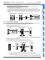
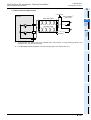
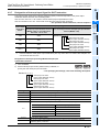
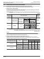
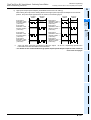
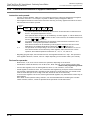
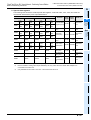
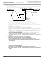
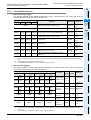
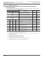
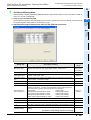
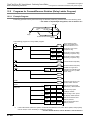
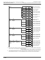
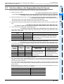
8) Creep speed
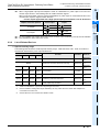
Use the devices shown in the following table to set the creep speed. Be sure to set the creep speed so
that the relation with the other speeds is "bias speed ≤ creep speed ≤ maximum speed".
Pulse output
destination device
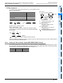
B - 92
Bias speed
Creep speed
Maximum speed
D1
= Y000
D8342
D8345
D8344,D8343
D1
= Y001
D8352
D8355
D8354,D8353
D1
= Y002
D8362
D8365
D8364,D8363
D1
= Y003
D8372
D8375
D8374,D8373
Initial value
1,000(Hz)