1
Chapter 6
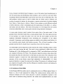
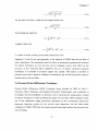
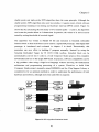
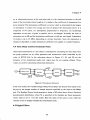
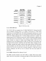
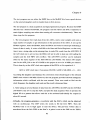
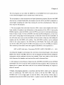
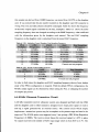
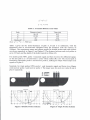
this sample rate derived from. EMIF frequency was tested from JIO P78 on the daughter
card. It was noticed that the pin number marked on the daughter card JIO connecter is
wrong. The even and odd columns should be exchanged. Table 6.2 shows the frequency
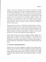
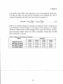
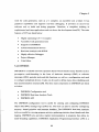
of the DAC output signal controlled by the PLL multiplier. Table 6.3 shows the DAC
sampling frequency does not changed according to the EMIF frequency, what conflicted
with the information given by the daughter card manual. The real DAC sampling
frequency on the daughter card is calculated from the tested DAC frequency.
Table 6. 2 PLL Multiplier Control Daughter Card Sampling Frequency
PLL
Multiplier
9 (default)
CPU
Frequency
225MHz
^^^^^^^^^^^^ L 250 MHz
11
275 MHz
i 300MHz
325 MHz
350 MHz
375 MHz
13
15
EMIF
Frequency
90 MHz
DAC
Frequency
33.33 kHz
100 MHaHiH36.9 kHz
Real Sampling ^
Frequency
8 MHz
8.9MHzH
9.7 MHz
10.7 MHz
12 MHz
110 MHz
40.59 kHz
120 MHz
44.44 kHz
130 MHz
50.10 kHz
HOMHzfl B
• FPGA FIFO Overflow
150 MHz
Cannot run test program
"|H
Table 6. 3 PLL Divider Control EMIF Frequenc>
*
PLL
Divider(div3)
5
• B
4
3
DAC
9 HlReal Sampling MM
Frequencyfjg
Frequency ^ilW
33.33 kHz
8 MHz
EMIF
Frequency
90 MHz
112.5 MHz
150 MHz
33.33 kHz
' " ^ ^^ 8 MHz
Cannot run test program
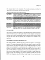
In order to find where the daughter card DAC sampling frequency derives from, further
study of the FPGA configuration is required. With the default FPGA configuration, the
40 kHz output signal can be obtained by either setting the PLL or changing the number
of samples per period.
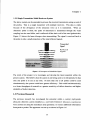
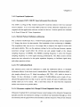
6.4 40 kHz Ultrasonic Transceiver Circuit
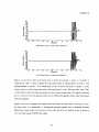
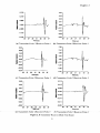
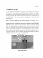
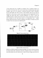
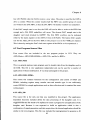
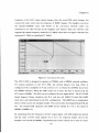
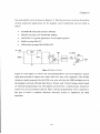
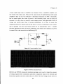
A 40 kHz transmitter-receiver ultrasonic system was designed and built with the DSK
and the daughter card to either transmit a designed wave shape pulse signal or receive
and log a signal generated by an external source. The current circuit which simply
implements a transceiver system may be incomplete at the present stage and need to be
improved. The 40 kHz pulser was triggered every 5 ms, giving a PRE (Pulse Repetition
Frequency) of 200Hz. The receive circuit biases the received signal to 1.65V to place
AC signal received in the middle of ADC input range which is from 0.6V to 2.7V. The
86