1
8
<<Contents>> <<Index>>
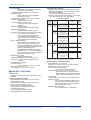
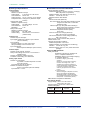
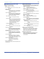
Isolation
Insulation resistance:
20 M min. between each terminal and
ground (at 500 V DC)
Withstanding voltage:
Between power supply terminal and ground:
1500 V AC (50/60 Hz), 1 min
Between relay contact output terminal and ground:
1500 V AC (50/60 Hz), 1 min
Between measurement input terminal and ground:
1500 V AC (50/60 Hz), 1 min
Between measurement input terminals:
1000 V AC (50/60 Hz), 1 min
Between contact input terminal and ground:
500 V DC, 1 min
Between current output terminal and ground:
500 V AC (50/60 Hz), 1 min
Between voltage pulse output terminal and ground:
500 V AC (50/60 Hz), 1 min
Between transistor contact output terminal and ground:
500 V DC, 1 min
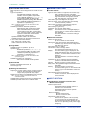
Grounding: Grounding resistance, less than 100 Control input terminals:
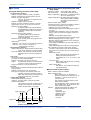
Isolated from other input/output terminals,
with inter-channel isolation.
Measurement inputs:
Isolated from other input/output terminals,
with inter-channel isolation (b terminal is
common for optional RTD).
Voltage pulse control output terminals*:
Not isolated from DC output terminals but
isolated from other input/output terminals.
Current output terminals*: Not isolated from voltage
pulse control output terminals but isolated
from other input/output terminals.
Control output (relay) terminals*:
Isolated from other input/output terminals.
Contact input terminals: Not isolated from other
contact input terminals but isolated from
other input/output terminals.
Contact output (relay) terminals:
Isolated from other input/output terminals.
Contact output (transistor) terminals:
Not isolated between transistor but
isolated from other input/output terminals.
Alarm output terminals:
Isolated from other input/output terminals.
Alarm remote terminals: Not isolated from DI but
isolated from other input/output terminals.
RS-232C: Not isolated from case.
RS-422/485:
Isolated from other input/output terminals.
Ethernet: Isolated from other input/output terminals.
Power terminals:
Isolated from other input/output terminals.
Grounding terminals: At case potential.
*: Control outputs have inter-loop isolation.
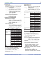
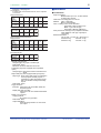
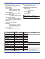
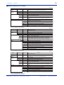
● Standard Performance Data
Input Type
DC voltage
(DCV)
Thermocouple
(TC) - excluding
the accuracy of
reference
junction
compensation
Resistance
temperature
detector (RTD)
Range
20 mV
60 mV
200 mV
2V
6V
20 V
50 V
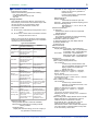
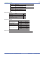
Measurement Accuracy (Digital Readings)
±(0.1% of rdg + 2 digits)
±(0.1% of rdg + 3 digits)
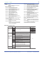
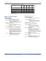
R
S
B
±(0.15% of rdg + 1°C), where R and S = ±3.7°C over 0 to
100°C and ±1.5°C over 100 to 300°C; B = ±2°C over 400 to
600°C, and is not guaranteed for temperatures below 400°C.
K
±(0.15% of rdg + 0.7°C), where the accuracy is ±(0.15% of
rdg + 1°C) over -200 to -100°C.
E
±(0.15% of rdg + 0.5°C)
J
T
±(0.15% of rdg + 0.5°C), where the accuracy is ±(0.15% of
rdg + 0.7°C) over -200 to -100°C.
N
W
±(0.15% of rdg + 0.7°C)
±(0.15% of rdg + 1°C)
L
U
±(0.15% of rdg + 0.5°C), where the accuracy is ±(0.15% of
rdg + 0.7°C) over -200 to 100°C.
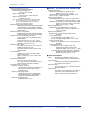
PLATINEL
0.0 to 1400.0°C
PR40-20
Not guaranteed over 0 to 450°C
±(0.9% of rdg + 16.0°C) over 450 to 750°C
±(0.9% of rdg + 6.0°C) over 750 to 1100°C
±(0.9% of rdg + 2.0°C) over 1100 to 1900°C
W3Re/
W25Re
±(0.3% of rdg + 2.8°C)
Pt100
JPt100
Max. resolution
of digital display
10 µV
10 µV
100 µV
1 mV
1 mV
10 mV
10 mV
0.1°C
±(0.15% of rdg + 0.3°C)
All Rights Reserved. Copyright © 2001, Yokogawa Electric Corporation
GS 04L31A01-01E
3rd Edition May.20,2003-00